Dynamic performance monitoring-based approach to memory management

a memory management and performance monitoring technology, applied in the field of memory management, can solve the problems of memory stall, memory speed may not improve, clock speed is not only affected, and memory stall is not known

Inactive Publication Date: 2006-06-29
INTEL CORP
View PDF6 Cites 39 Cited by
  • Summary
  • Abstract
  • Description
  • Claims
  • Application Information

AI Technical Summary

Problems solved by technology

A well-known performance gap exists between microprocessor speed and memory performance.
Microprocessor clock speeds double every few years, while memory speeds may hardly improve.
And the performance gap is not only from clock speed, but also from latency problems and memory stalls.
Unfortunately, Level 1 and Level 2 cache memories are plagued with latency problems and memory stalls waiting for memory from RAM.
Larger cache memories, for example, experience greater read and write latencies, greater data translation look aside buffer (DLTB) misses, and greater cache miss information.
Garbage collectors that fragment memory by limiting where an object can be allocated harm object allocation times and may lead to greater DTLB misses.
Yet, despite its performance advantages, sliding compaction is quite expensive in comparison to some other garbage collection routines imposing significant space and time overheads on all phases of garbage collection.
These problems are exacerbated with large heap sizes.
Even, incremental sliding compaction, i.e., sliding only a portion of the heap during a given garbage collection cycle, is unable to get to the problem areas quickly enough, as many memory regions must wait numerous collection cycles before being managed.
In the end, memory latency and stalls place a high tax on current memory management techniques.
Identifying problematic memory regions must be done each time a code is executed and reclamation of the memory spaces within these problematic regions, especially for larger heaps, is too imprecise for efficient code implementation.

Method used


Image

  • Dynamic performance monitoring-based approach to memory management
  • Dynamic performance monitoring-based approach to memory management
  • Dynamic performance monitoring-based approach to memory management

Examples


Embodiment Construction

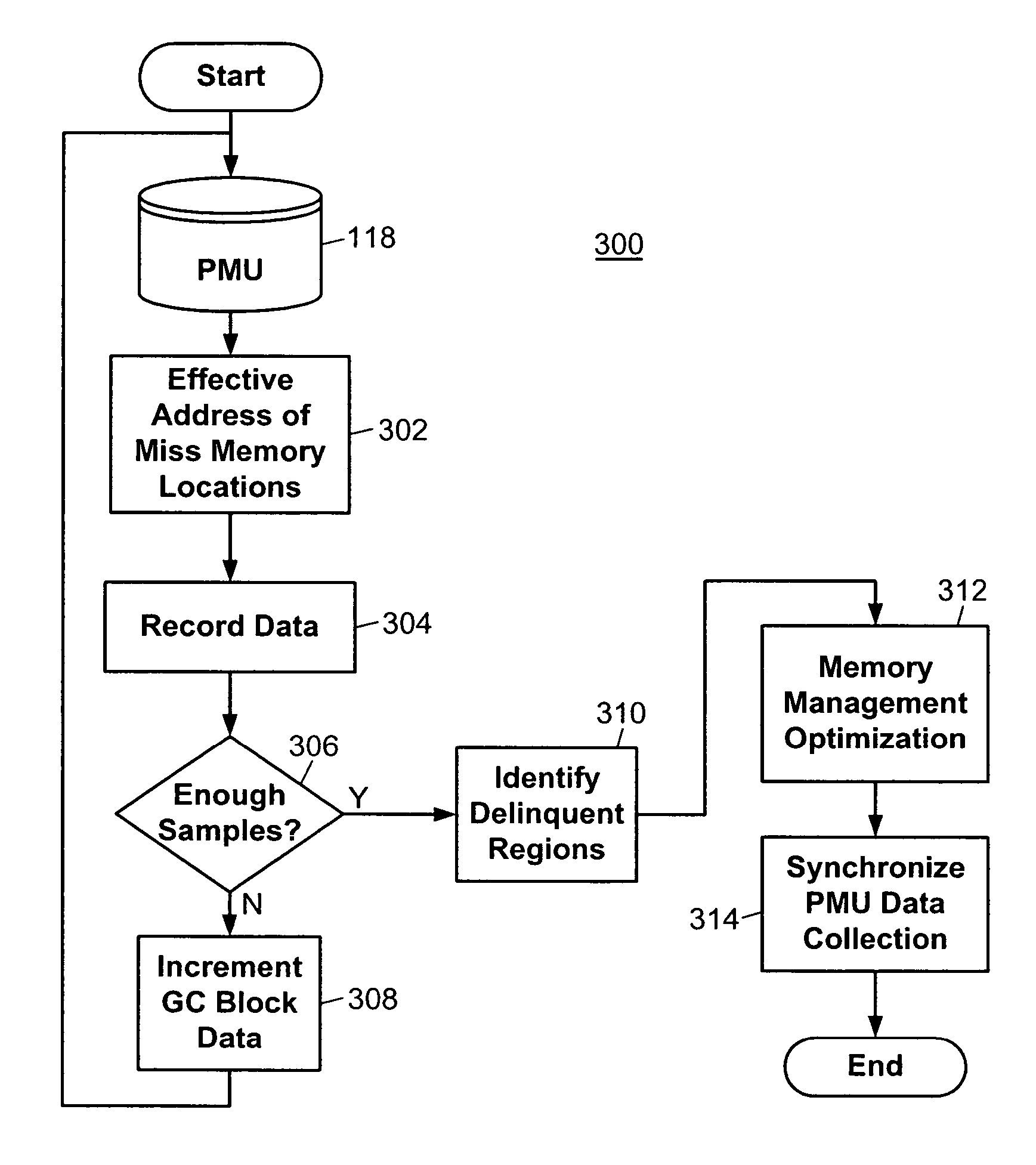
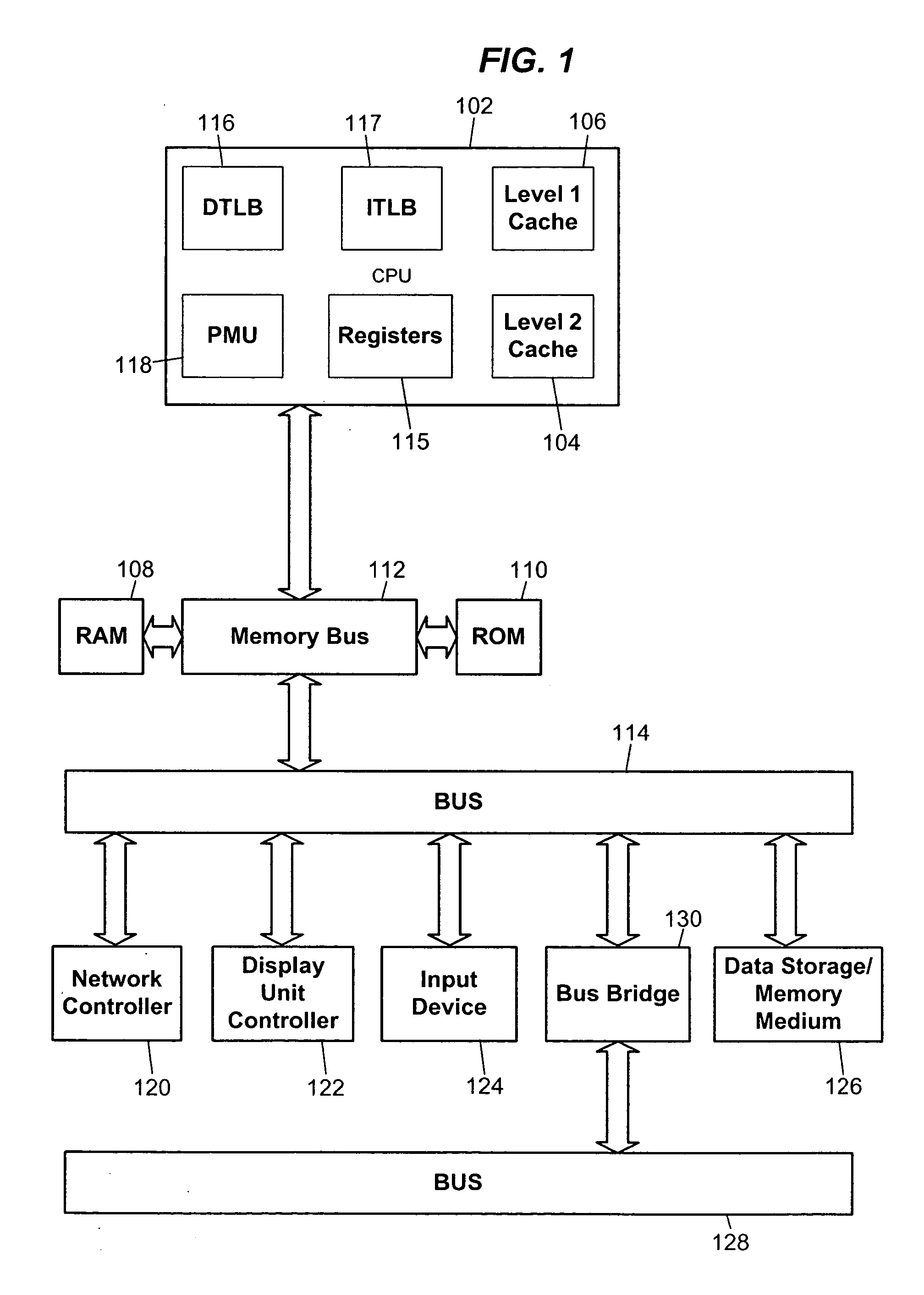
[0019] Various techniques are described for optimizing memory management within a processor system. By focusing the work performed by memory management, the execution of application code, i.e., mutators, in dynamic managed runtime environments like Java and .Net environments running on the processor system may be improved. The techniques may be implemented on processors or processor architectures capable of performance monitoring by using hardware monitoring. Sample microprocessors included Pentium® 4 (Precise Event Based Sampling) and Itanium® processors (Performance Monitoring Unit) available from Intel Corporation of Santa Clara, Calif. The techniques may be implemented into dedicated processor environments, as well, of which the input / output (I / O) processors used in storage, networking and embedded applications are examples. In I / O applications, e.g., servers, workstations, and storage subsystems, the techniques may be realized to optimize memory management across a network of d...


PUM


Abstract

Techniques are described for optimizing memory management in a processor system. The techniques may be implemented on processors that include on-chip performance monitoring and on systems where an external performance monitor is coupled to a processor. Processors that include a Performance Monitoring Unit (PMU) are examples. The PMU may store data on read and write cache misses, as well as data on translation lookaside buffer (TLB) misses. The data from the PMU is used to determine if any memory regions within a memory heap are delinquent memory regions, i.e., regions exhibiting high numbers of memory problems or stalls. If delinquent memory regions are found, the memory manager, such as a garbage collection routine, can efficiently optimize memory performance as well as the mutators performance by improving the layout of objects in the heap. In this way, memory management routines may be focused based on dynamic and real-time memory performance data.

Description

FIELD OF THE DISCLOSURE [0001] The disclosure generally relates to memory management in a processor-based system and, more particularly, to apparatuses and techniques for optimizing memory management. BACKGROUND OF THE RELATED ART [0002] A well-known performance gap exists between microprocessor speed and memory performance. Microprocessor clock speeds double every few years, while memory speeds may hardly improve. A microprocessor might operate at GHz clock speeds, while the random access memory (RAM) used by that microprocessor has clock speeds an order of magnitude slower, at least. Consumers can intuitively appreciate that the performance gap affects mass storage memory, like hard drives and CD-ROM storage, but the gap affects faster memories like RAM and cache, as well. And the performance gap is not only from clock speed, but also from latency problems and memory stalls. [0003] Computer systems use multiple memory levels to address the performance gap. Each level is closer to ...

Claims


Application Information

Patent Timeline
Patent Type & Authority Applications(United States)
IPC IPC(8): G06F12/00G06F11/34G06F12/02
CPCG06F11/348G06F12/0253G06F12/0269G06F2201/88G06F2201/885Y10S707/99957
Inventor SUBRAMONEY, SREENIVASHUDSON, RICHARDSERRANO, MAURICIOADL-TABATABAI, ALI-REZA
Owner INTEL CORP
Why Eureka
Try Eureka