Lined pressure vessel and connector therefor

a technology for pressure vessels and connectors, applied in the direction of vessel construction details, container discharging methods, transportation and packaging, etc., can solve the problems of limiting the types of coatings that may be applied to the interior of a closed vessel, and affecting the service life of the vessel

Inactive Publication Date: 2006-07-06
AMTROL LICENSING INC
View PDF20 Cites 44 Cited by
  • Summary
  • Abstract
  • Description
  • Claims
  • Application Information

AI Technical Summary

Benefits of technology

[0013] The subject invention is directed to a unique pressure vessel, which combines the strength of a metallic tank with the interior passivity of a plastic tank. The pressure vessel comprises a lower metallic dome having a lower rim portion, an upper metallic dome having an upper rim portion, and a plastic liner disposed within the upper and lower metallic domes. A metallic band is disposed between the plastic liner and the upper and lower metallic domes proximate the respective rim portions thereof, and an insulating material is disposed between the metallic band and the plastic liner. The metallic band and insulating material protect the plastic liner from elevated temperatures that are presented when the upper and lower rim portions of the metallic domes are welded together.

Problems solved by technology

Any damage or discontinuity in the lining could result in the eventual contamination of the contents of the tank and corrosion of the exterior metal components.
However, this limits the types of coatings that may be applied to the interior of a closed vessel.
The process is also time consuming and expensive, and there is no assurance that the lining will completely cover the interior of the vessel as intended.
However, the purpose of this insulating band is not to protect the lining of the tank, but to prevent the current generated by the electric welding process from jumping to an adjacent metallic wall.
Another problem associated with manufacturing a pressure vessel with an external metallic tank and a non-corrosive internal plastic liner is providing a cost efficient means for connecting the two structures together to form an integral vessel.
However, many are susceptible to leakage.
Leakage at the connector can cause corrosion of the metallic components of the pressure vessel and can damage system components carrying fluid to and from the pressure vessel.

Method used


Image

  • Lined pressure vessel and connector therefor
  • Lined pressure vessel and connector therefor
  • Lined pressure vessel and connector therefor

Examples


Embodiment Construction

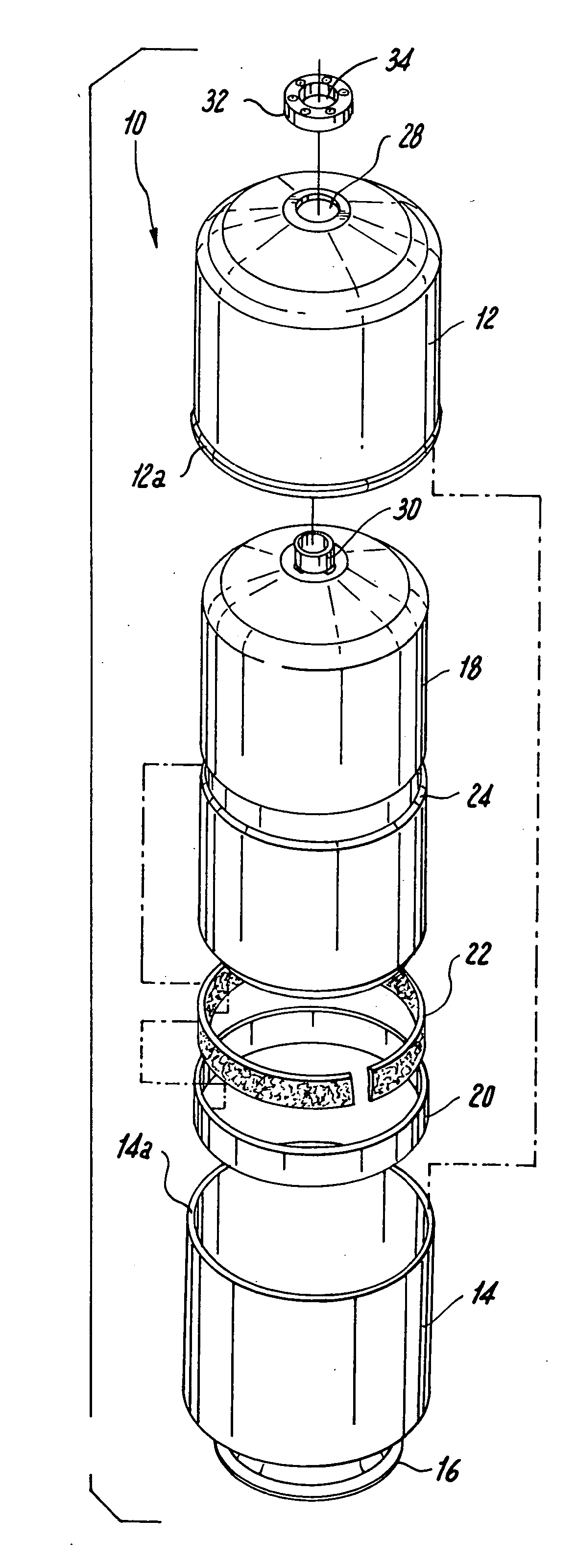
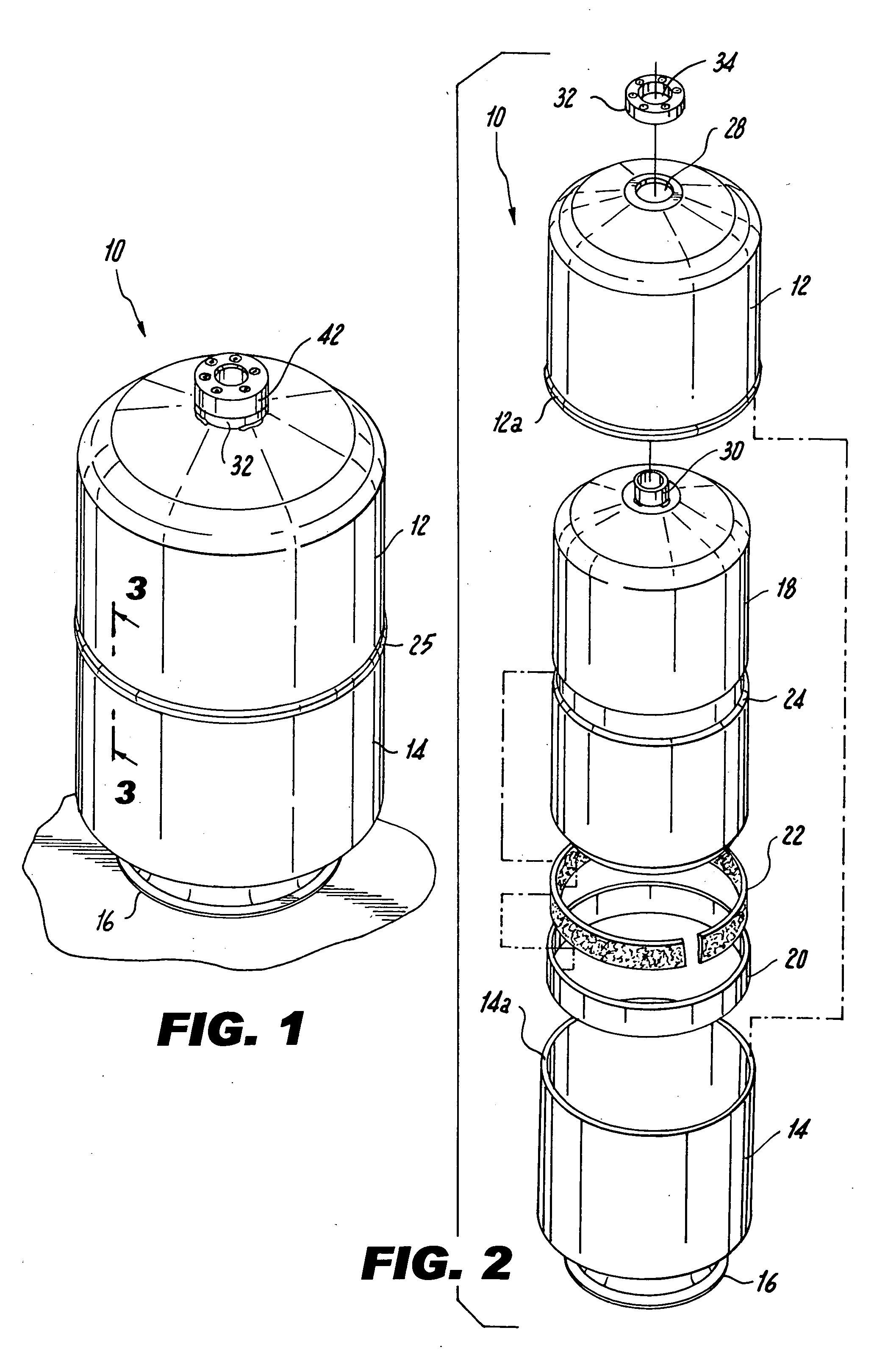
[0029] Referring now to the drawings wherein like reference numerals identify similar aspects and / or features of the subject invention there is illustrated in FIG. 1 a pressure vessel configured in accordance with a preferred embodiment of the subject invention and designated generally by reference numeral 10.

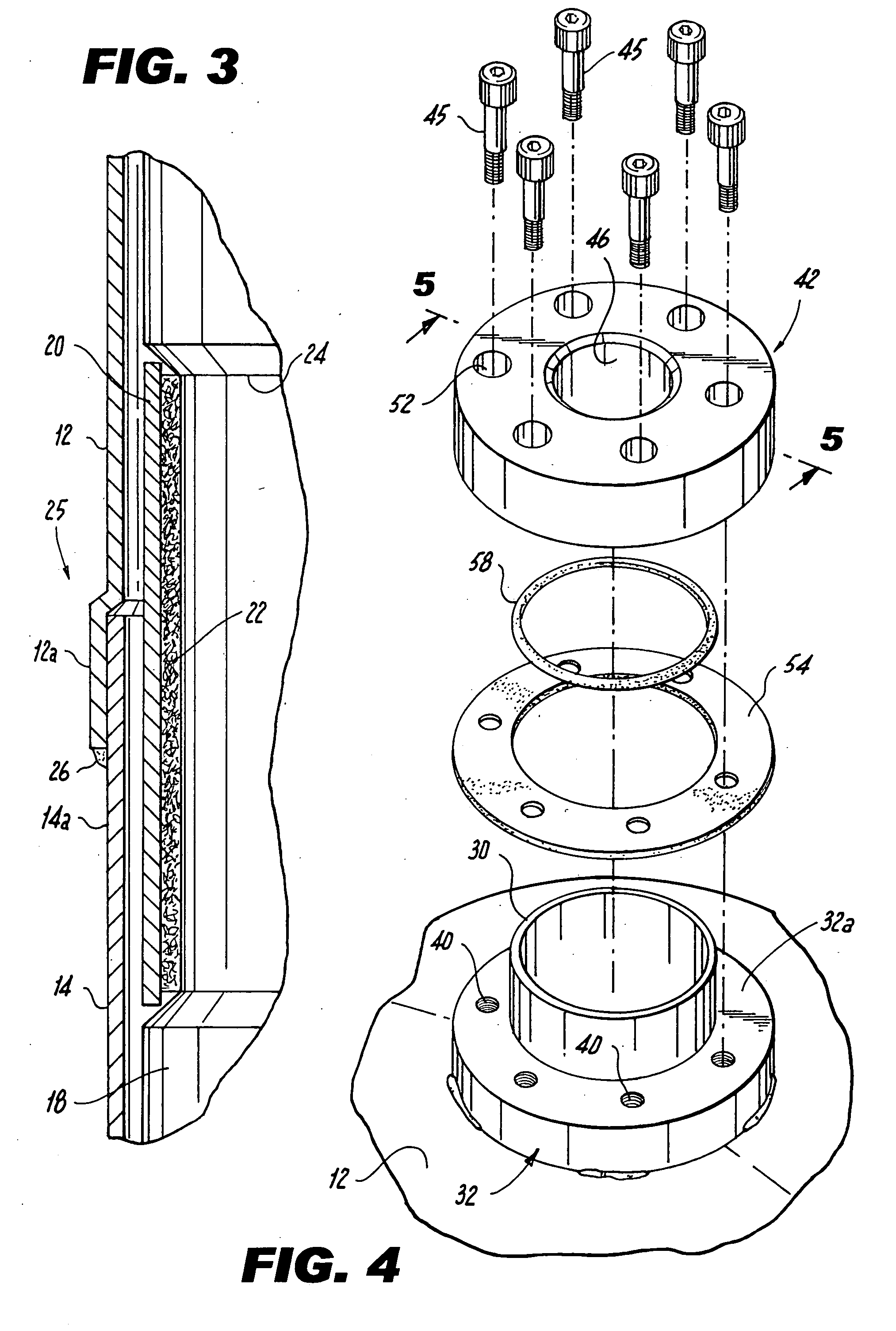
[0030] Referring to FIGS. 1 and 2, pressure vessel 10 includes an upper metallic dome 12 having an upper rim portion 12a, a lower metallic dome 14 having a lower rim portion 14a. The upper and lower metallic domes 12, 14 are preferably formed from high strength structural steel or a similar material. The lower metallic dome 14 includes a cylindrical base or platform 16 for supporting the pressure vessel 10 on a surface. A molded plastic liner 18 is disposed within the upper and lower metallic domes 12, 14. The plastic liner 18 acts as a barrier between the external steel domes 12, 14 and the internal fluid. Consequently, pressure vessel 10 combines the strength of an external ...


PUM

PropertyMeasurementUnit
pressureaaaaaaaaaa
metallicaaaaaaaaaa
temperaturesaaaaaaaaaa

Abstract

A pressure vessel is disclosed which includes a lower metallic dome having a lower rim portion, and an upper metallic dome having an upper rim portion, a plastic liner disposed within the upper and lower metallic domes, a metallic band disposed between the plastic liner and the upper and lower metallic domes proximate the respective rim portions thereof, and an insulating material disposed between the metallic band and the plastic liner, the metallic band and insulating material protecting the plastic liner from elevated temperatures when the upper and lower rim portions of the metallic domes are welded together. A method of fabricating the pressure vessel and a connector for assembling the pressure vessel are also disclosed.

Description

BACKGROUND OF THE INVENTION [0001] 1. Field of the Invention [0002] The subject invention relates to pressure vessels for fluid storage, and more particularly to a metallic tank having a molded plastic liner, a thermal barrier for protecting the plastic liner during assembly of the vessel, and a connector for joining the metallic tank and plastic liner together. [0003] 2. Background of the Related Art [0004] Pressure vessels that combine the strength of an exterior metallic tank and the passivity of an interior plastic liner are well known in the art. Such tanks have achieved widespread usage in the field of domestic fluid storage, including hot water storage tanks, hot water heating tanks and accumulators for hot water heating systems. [0005] Because of the enclosed nature of these pressure vessels, they are more easily fabricated in several sections, which are subsequently welded together. However, great care must be taken when welding the tank sections together, to avoid damaging...

Claims


Application Information

Patent Timeline
Patent Type & Authority Applications(United States)
IPC IPC(8): F17C1/02
CPCF17C1/02F17C13/06F17C2201/0109F17C2201/032F17C2201/056F17C2203/0329F17C2203/0345F17C2203/0604F17C2203/0619F17C2203/0636F17C2203/0639F17C2203/066F17C2205/018F17C2205/0305F17C2205/0394F17C2209/221F17C2209/228F17C2209/232F17C2221/03F17C2223/035F17C2260/036F17C2260/044F17C2260/053F17C2270/07
Inventor VANDAL, PETER J.MURDOCK, BRUCEVANHAAREN, CHRISTOPHER A.
Owner AMTROL LICENSING INC
Why Eureka
Try Eureka