
System and method for detecting an object on a moving web

a technology of a web and an object, applied in the field of system and method for detecting an object on a moving web, can solve the problems of slitting a product to the wrong width, adhesive off the edges of the web, and failing to make a product to the target dimension, etc., to achieve the effect of convenient monitoring and convenient placemen

Inactive Publication Date: 2006-07-06
KIMBERLY-CLARK WORLDWIDE INC
View PDF10 Cites 5 Cited by
  • Summary
  • Abstract
  • Description
  • Claims
  • Application Information

AI Technical Summary

Benefits of technology

The present invention is a system and method for detecting objects on a moving web using gradient-indexed optics. The system includes a light source, a lens with a radial index of refraction gradient, and a sensor that converts the light to a signal. The signal can be used to adjust the position of the objects on the web. The technical effects of the invention include improved detection of objects on a moving web and easier placement of sensors in confined areas.

Problems solved by technology

When a web is moving at high speeds it is important to make sure the web, and any objects that are on the web, are properly aligned or there may manufacturing problems.
Some example manufacturing problems include slitting a product to the wrong width, spraying adhesive off the edges of the web, or failing to make a product to its targeted dimensions (among other problems).
One of the drawbacks with sensors which include cylindrical or spherical lenses is that the cylindrical or spherical lenses require a relatively large focal distance in order to properly focus light onto the light detector.
This relatively large focal distance often makes it difficult to place the sensors in confined areas.
Another drawback with these types of sensors relates to establishing a field of view for the sensor because it is often necessary to zoom in on to a small detection area in order to get sufficient pixel resolution for the light detector within the sensor.
Therefore, many sensors are limited to applications where the position of the web and / or the objects on the web does not vary position by more than a certain amount.
These types of sensors are also limited in their ability to detect objects on a moving web, especially when the objects and the web are similar colors and / or opacities.
Most sensing systems are not sophisticated enough to adequately sense such objects on these types of webs.

Method used


Image

  • System and method for detecting an object on a moving web
  • System and method for detecting an object on a moving web
  • System and method for detecting an object on a moving web

Examples


Embodiment Construction

[0023] The present invention relates to a system and method for detecting objects on a moving web. The system and method are well suited for detecting objects on a web when physical space limitations are such that other systems and methods cannot be used effectively.

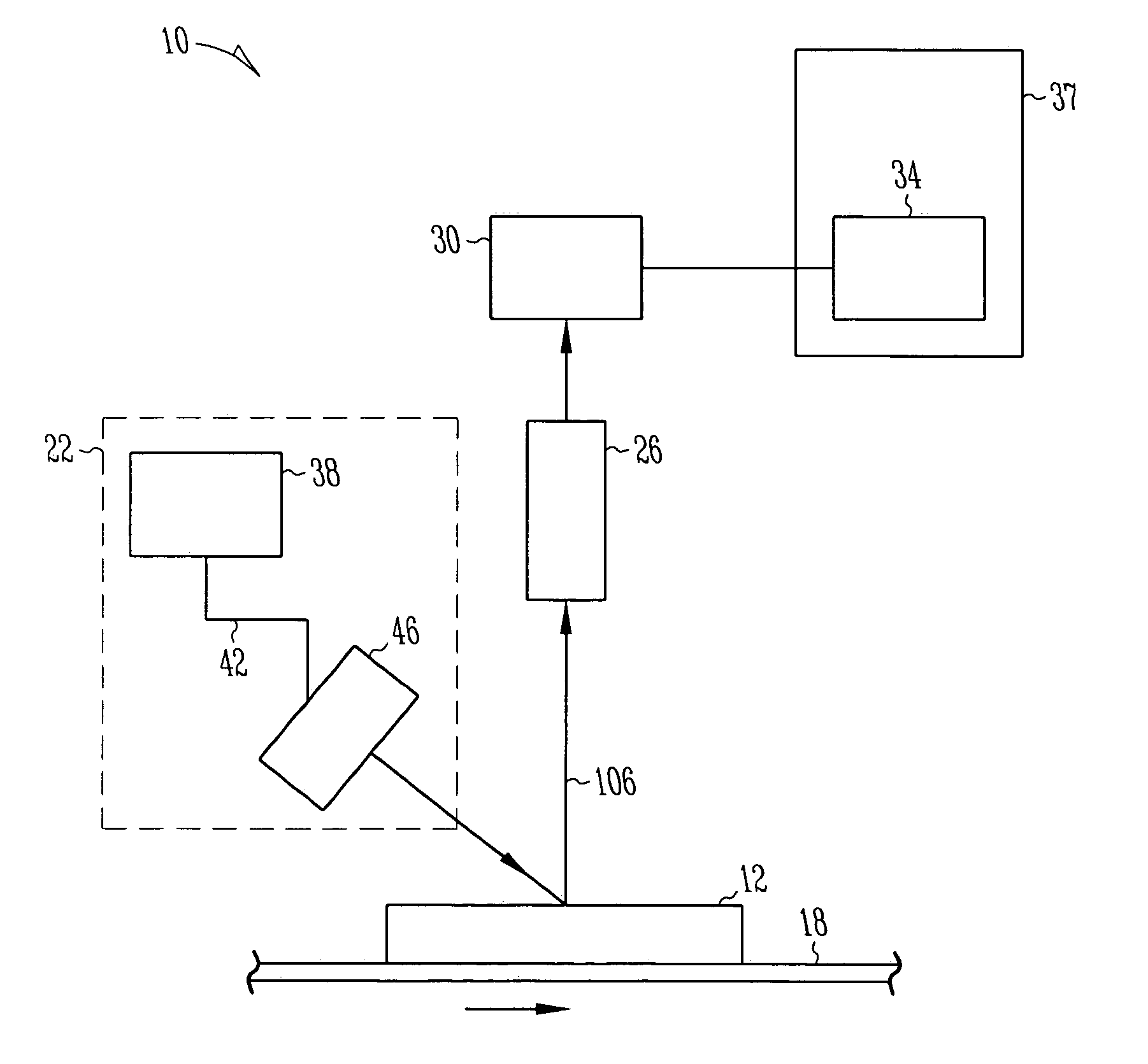
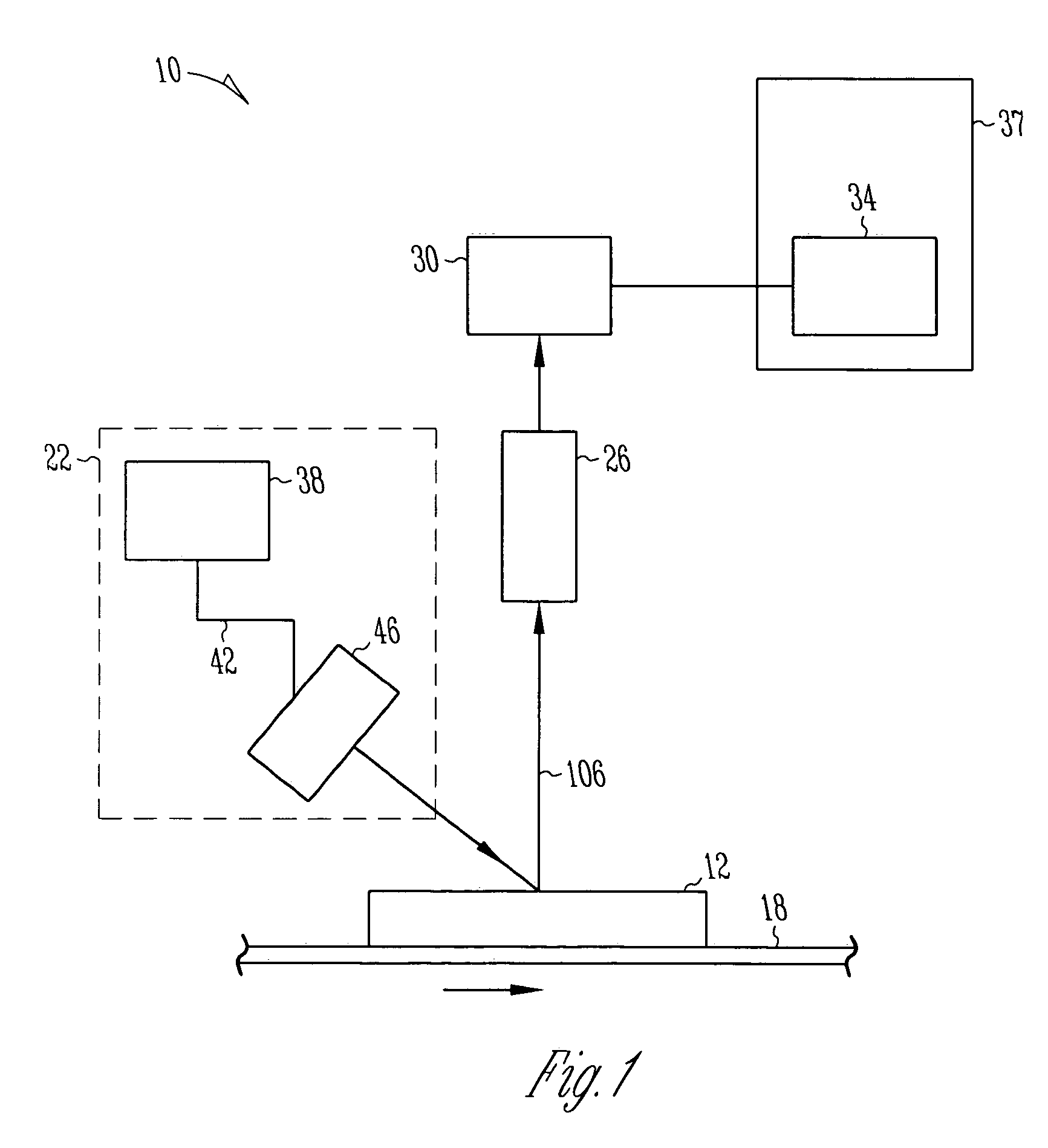
[0024]FIG. 1 shows a system 10 which may be used to detect an object 12 that is on a moving web 18. The system 10 includes a light source 22, a lens 26 and a sensor 30. Although only one object 12 is shown on web 18 in FIG. 1, the system 10 may be used to detect any number of objects 12 on the web 18. It should be noted that the objects 12 may be arranged on the web 18 in any orientation or spacing.

[0025] The light source 22 may include an illuminator 38 that is connected through a fiber optic cable 42 to a fiber optic light line 46. The light that is generated by the illuminator 38 is transmitted through the fiber optic cable 42 to the fiber optic light line 46. The fiber optic light line 46 is positioned adjacent to ...


PUM

PropertyMeasurementUnit
radial index of refractionaaaaaaaaaa
shapeaaaaaaaaaa
widthaaaaaaaaaa

Abstract

The system includes a light source that emits light onto a web and objects that are on the web. The system further includes a lens that has a radial index of refraction gradient. The lens is positioned such that the lens only captures light above a nominal level when light from the light source is reflected by the objects and not the web. A sensor receives light from the lens and converts the light to a signal. The method includes directing light onto the objects and the web using a light source. The method further includes positioning a lens that has a radial index of refraction gradient relative to the web and the light source such that the lens only captures light above a nominal level when the light from the light source is reflected by the objects. The method further includes focusing the captured light on a sensor.

Description

FIELD OF THE INVENTION [0001] The present invention relates to a system and method for detecting an object on a moving web, and in particular to a system and method that use gradient-indexed optics to detect an object on a moving web. BACKGROUND OF THE INVENTION [0002] A web is a flexible piece of material that has a width and thickness which are significantly smaller than the length of the web. Webs are used in many manufacturing processes to produce products efficiently (e.g., tissue, sheet metal, and films). [0003] Most webs are conveyed at high speeds in order to produce high volumes of products. When a web is moving at high speeds it is important to make sure the web, and any objects that are on the web, are properly aligned or there may manufacturing problems. Some example manufacturing problems include slitting a product to the wrong width, spraying adhesive off the edges of the web, or failing to make a product to its targeted dimensions (among other problems). [0004] The al...

Claims


Application Information

Patent Timeline
Patent Type & Authority Applications(United States)
IPC IPC(8): G01N21/86G01V8/00
CPCG01N21/89G01N2021/8908G01N2201/0826G01V8/10
Inventor SOREBO, JOHN H.
Owner KIMBERLY-CLARK WORLDWIDE INC
Learn More