

Folded self-adhesive label
a self-adhesive label and label technology, applied in the field of labels, can solve the problems of not being suitable for use as labels, and achieve the effects of convenient opening for users, simple application, and low manufacturing cos
- Summary
- Abstract
- Description
- Claims
- Application Information
AI Technical Summary
Benefits of technology
Problems solved by technology
Method used
Image

Examples
first embodiment
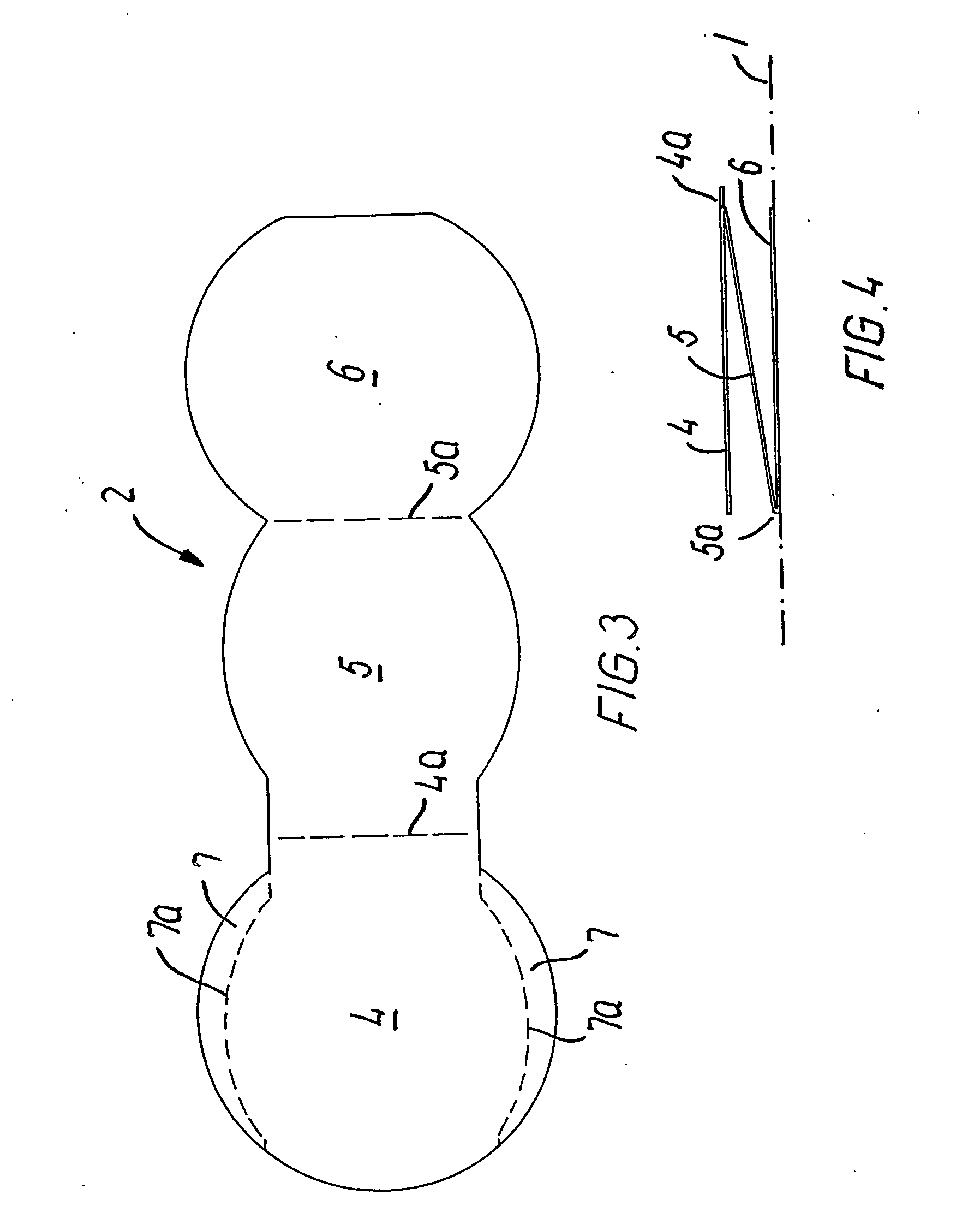
[0028] The first embodiment is shown in FIG. 3, which shows the configuration of the basic label as it appears after the punching.
[0029] It comprises three parts, viz. a bottom part 6, a folding part 5 and a top part 4. It is characteristic of these parts that they have different shapes, and that they are provided with two bending lines 4a and 5a which separate the parts, and moreover with perforations 7a in the top part 4.
[0030] When the extent of the bottom part 6 has been determined, the top part 4 is dimensioned correspondingly, as these two parts 4 and 6 are to be disposed over each other when the package has been folded.
[0031] The folding part 5 has a smaller extent than the top and bottom parts such that when the folding part 5 has been folded in and the label assembled, as indicated in FIG. 4, which shows the label during folding, the folding part 5 will extend between the bottom part 6 and the top part 4 within the area defined by the perforations 7a.
[0032] The purpose o...
second embodiment
[0035] The second embodiment is shown in FIGS. 5 and 6.
[0036] The starting label is shown in FIG. 5 and differs from the first embodiment in that further folding parts 11, 12 have been added to the left in the figure from the top part 6, so that this example includes a total of five faces for printing / imaging.
[0037] Tearing of the part serving as a seal of the package is at a perforation 13a in the top part 10 in this case.
[0038]FIG. 6 indicates the folding principle, comprising two folding operations, viz. partly the folding of the folding parts 11, 12 inwards below the top part 10, following which the top part 10 with the folding part 9 may be folded and the protruding portions of the top part may be adhered to the protruding portions 13 of the bottom part.
[0039] Since, in this example too, the folding edge 10a protrudes slightly forwardly of the bottom part 8, it will form a flap of two adhered package layers which protrudes above the package, and which may be used for tearing...
third embodiment
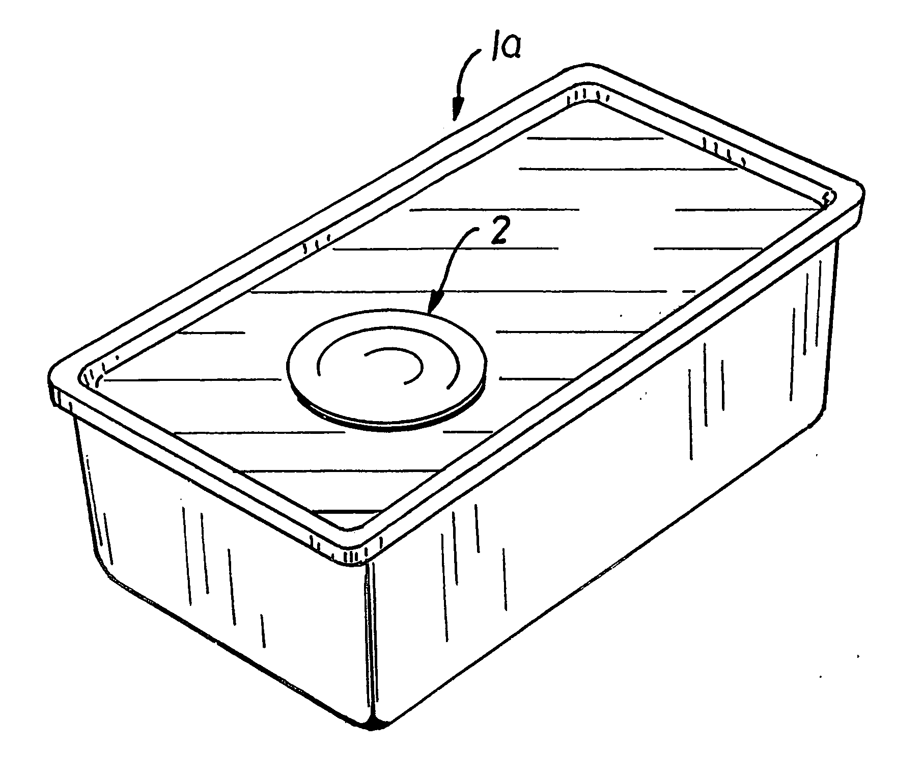
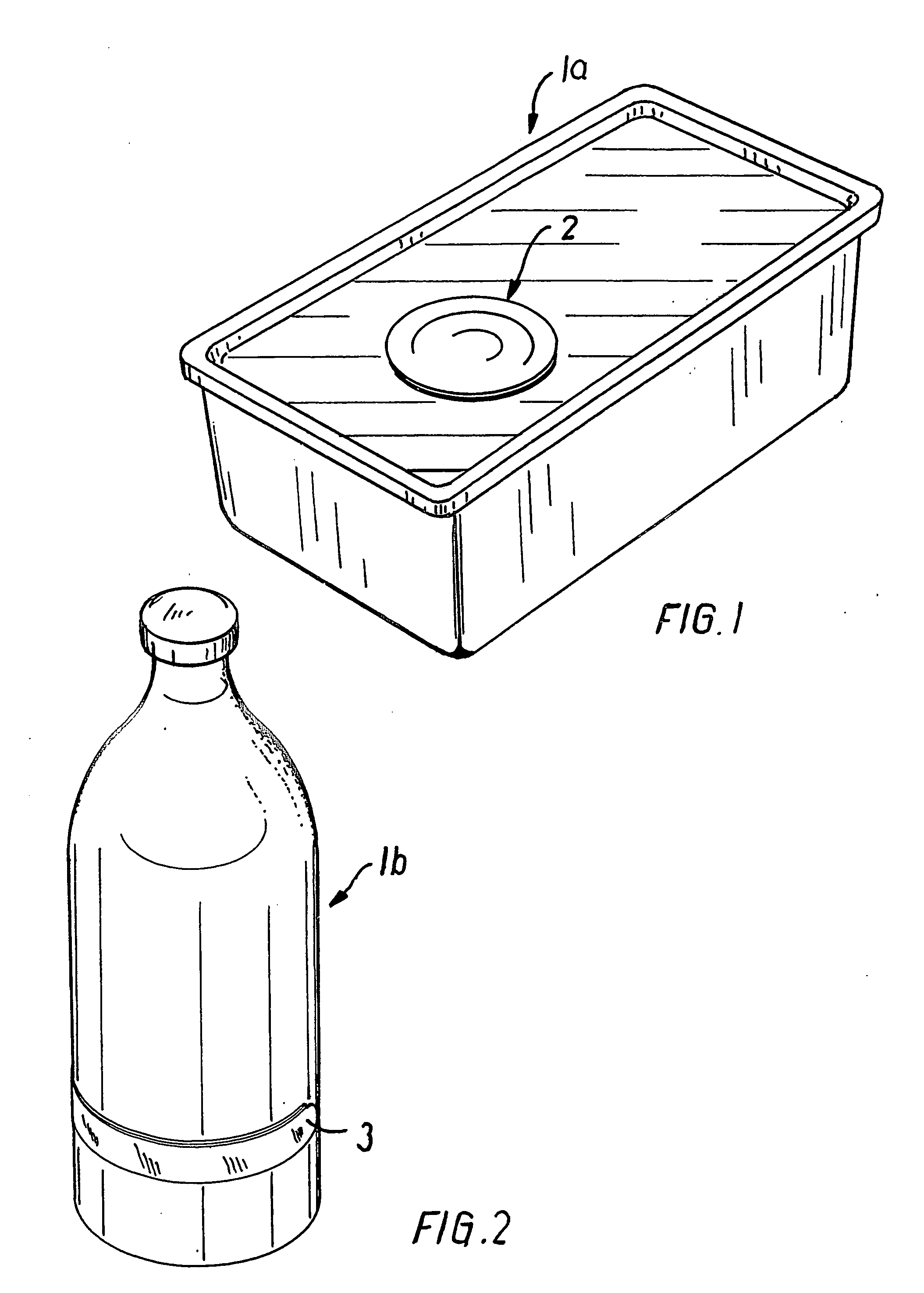
[0041] The third embodiment is shown in FIGS. 7 and 8. As indicated in FIG. 2, this embodiment is particularly suitable for adhesion to curved surfaces, such as a can or a bottle 1b.
[0042] The starting point is the basic workpiece shown in FIG. 7 which comprises elongated parts.
[0043] The parts are formed by a bottom part 16 which is additionally connected on both sides with a folding part 17 and a top part 18 disposed at the bottom of FIG. 7 and two folding parts 15 and 18 disposed at the top of FIG. 2.
[0044] All the bending lines, which are also tearing lines, extend in parallel and at the same mutual distance.
[0045] It is observed that all the folding parts 14, 15, 17 are slightly shorter than the top and bottom parts 18 and 16, which terminate in protruding portions 19 and 20, whose function will be described later.
[0046] The opposite end of the label is provided with protruding annular parts 21 on the top part 18 as well as on the two uppermost folding parts 14 and 15.
[00...
PUM
 Abstract
Description
Claims
Application Information