
Apparatus, method and program product for rearraging frames

a frame and rearrangement technology, applied in the field of rearrangement techniques of frames, can solve the problem of inability for users to know from which frame boundaries they could independently be moved, and achieve the effects of improving the operability of frames, reducing data visibility impairment, and improving the availability of data or documents

Inactive Publication Date: 2006-07-06
IBM CORP
View PDF5 Cites 34 Cited by
  • Summary
  • Abstract
  • Description
  • Claims
  • Application Information

AI Technical Summary

Benefits of technology

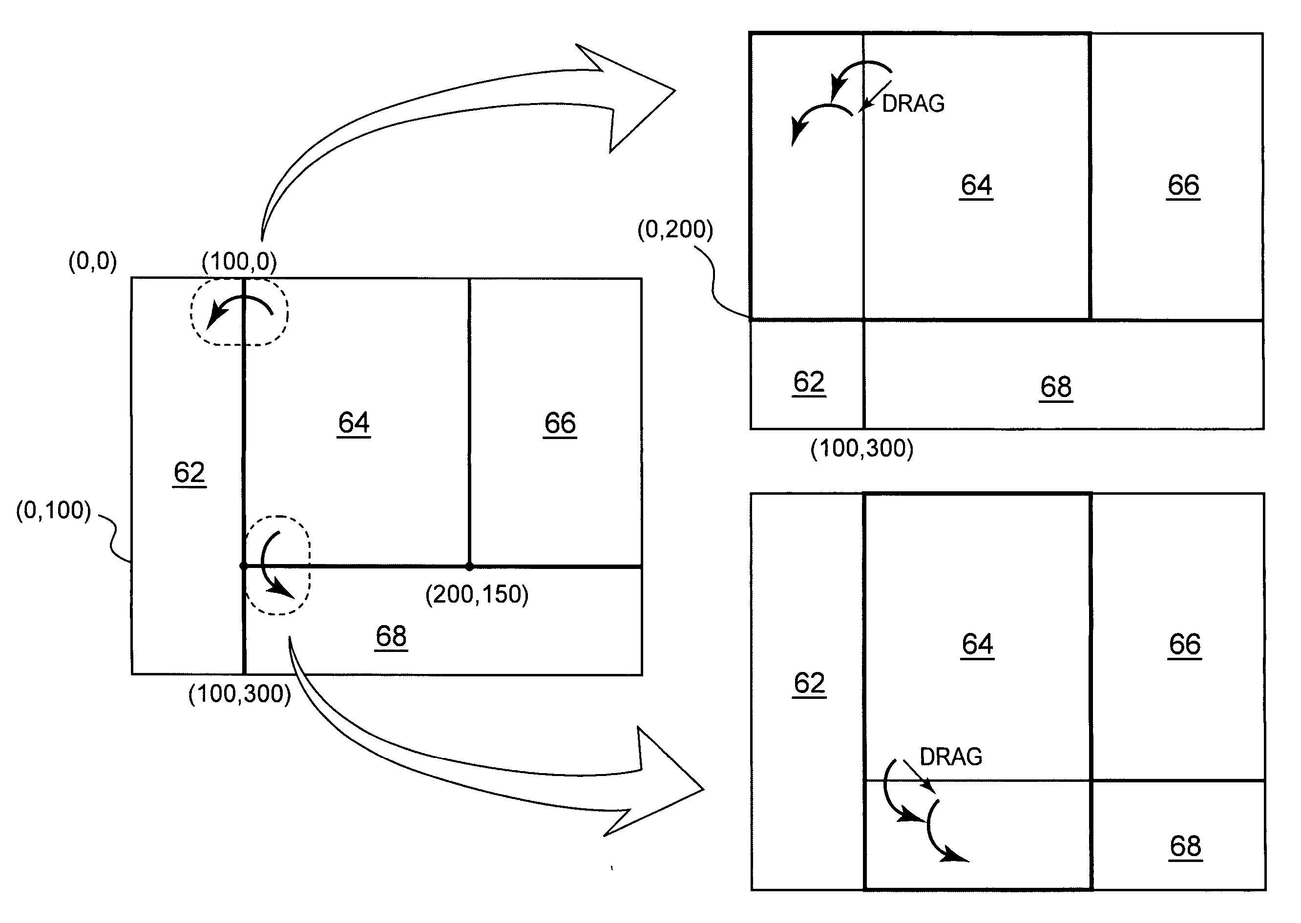
[0008] The present invention has been made in view of inconvenience of the aforementioned conventional art, and a size of a designated frame is changed by rotating a designated frame boundary of a plurality of frame boundaries formed in the window. For this reason, it is possible to rearrange the frame boundary while minimizing the effect on visibility of other frames. Further, according to the present invention, before the user fixes a change of the frame size, a predicted frame in which the frame size is changed is transitionally provided. For this reason, by confirming the predicted frame transitionally displayed on the display, the user can determine an area change of the frame boundary. Additionally, data that the user could not confirm without expanding the frame itself in the past can also be confirmed without changing the conventional frame arrangement.
[0009] More specifically, according to the present invention, except a frame boundary formed in contact with a window boundary, a specific end point where two or three frames of a plurality of frames formed within the window are collectively formed is identified. The frame size is changed by rotating at least one of the frame boundaries connected to the specific end point by 90 degrees around on the specific end point. Hereinafter, the end point allowing such rotation move is referred to as a two-degrees-of-freedom end. More specifically, the two-degrees-of-freedom end is referred to as an end point where two frame boundaries are collectively formed, or an end point of the frame where three frame boundaries are collectively formed. In other words, the two-degrees-of-freedom end means an end point having a phase characteristic in which quadrants formed by the frame boundaries are not decreased even when either of two frame boundaries is rotated by 90 degrees.
[0014] According to the present invention, it is possible to provide, while the user minimizes the visibility impairment of data or a document displayed on the frame, an information processing apparatus installing a graphical user interface capable of improving the operability of the frame, and in addition to that, capable of improving the availability of the data or the document by the user, a method thereof and a program thereof.

Problems solved by technology

However, it is impossible for the user to know from which one to which one of the frame boundaries could independently be moved and / or could be jointly moved only by changing the shape of the pointer cursor, as also shown in FIG. 10 and FIG. 11.

Method used


Image

  • Apparatus, method and program product for rearraging frames
  • Apparatus, method and program product for rearraging frames
  • Apparatus, method and program product for rearraging frames

Examples


Embodiment Construction

[0026] Hereinafter, the present invention will be explained, based on embodiments shown in the drawings, but the present invention is not limited to the embodiments described below.

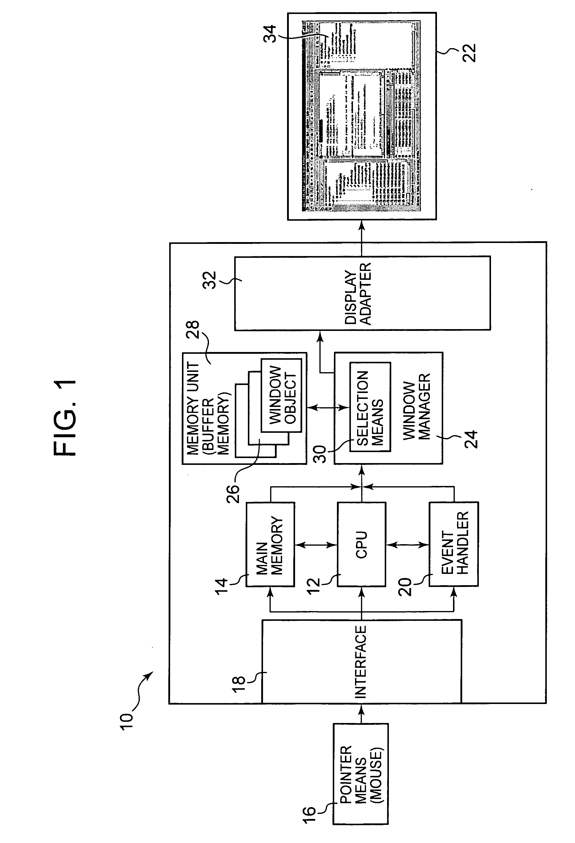
[0027]FIG. 1 is a block diagram showing a functional conFIGuration of an information processing apparatus 10 of the present invention. The information processing apparatus 10 of the present invention can be composed as a personal computer or a workstation, and mostly includes a CPU 12, a main memory 14, and an event handler module 20 that receives a signal from pointer means 16 such as a mouse, a stylus pen, or a touchpad, or a keyboard via an interface 18 to obtain positional information for calculating a motion vector. The information processing apparatus 10 further includes a window manager 24 that executes processing for specifying the generation and a size of a window displayed on a display unit 22 and generating a frame within the window. More specifically, the window manager 24 includes window obj...


PUM


Abstract

An apparatus including a display unit for rearranging frames in a window that includes an event handler module for processing position coordinate data on a window object displayed on the display unit; a frame boundary rotatable determination module that obtains position coordinate data of an end point of the frame boundary formed in the window object so as to determine that the end point is rotatable around a specific end point; and a layout manager for processing coordinate conversion of the specific end point to the end point determined as being rotatable, calculating position coordinate data for changing the frame boundary to generate a predicted window object to be displayed, and storing the predicted window object into a memory unit apart from the window object. A method of providing a graphical user interface and a program product for providing the graphical user interface comprising similar attributes is disclosed.

Description

CLAIM FOR PRIORITY [0001] This application claims the benefit of Japanese Patent Application No. 2005-000110, filed Jan. 4, 2005, which is hereby incorporated herein. FIELD OF THE INVENTION [0002] The present invention generally relates to a rearrangement technique of a frame displayed in a window, and more particularly relates to an information processing apparatus including a graphical user interface, which rearranges the frame without impairing visibility of a text displayed in a predetermined frame to a user, a frame rearrangement method, and a program thereof. BACKGROUND OF THE INVENTION [0003] With an increase in speed and high-performance of a computer, a plurality of frames are formed in one window at present, and while displaying different data or documents in respective frames, operations are executed in many cases. A method of changing a frame arrangement in a window, which has conventionally been used, is shown in FIG. 10 (see also, e.g., www.eclipse.org). Conventionally...

Claims


Application Information

Patent Timeline
IPC IPC(8): G09G5/397G06F3/048G06F3/0481G06F3/0487
CPCG06F3/0481
Inventor INOUE, MOTOHARUNAKAMURA, KOHICHI
Owner IBM CORP
Learn More