Focused state display device and focused state display method

a display device and focused state technology, applied in the field of apparatus for displaying the focus state of a camera and a display method thereof, can solve the problems of difficult adjustment of focus, difficult to focus, and difficult for users to understand the displayed focus sta

Active Publication Date: 2006-07-06
SHARP KK
View PDF13 Cites 142 Cited by
  • Summary
  • Abstract
  • Description
  • Claims
  • Application Information

AI Technical Summary

Benefits of technology

[0031] According to the aforementioned focus state determination apparatus, only those signals not less than a certain threshold value in the histogram are used for the f

Problems solved by technology

Thus, it has been difficult to focus while determining a blur of a photographing image, for example, with the naked eyes.
Also, even the focus state display apparatus as described in Patent Document 1 (JP Patent Publication (Ko

Method used


Image

  • Focused state display device and focused state display method
  • Focused state display device and focused state display method
  • Focused state display device and focused state display method

Examples


first embodiment

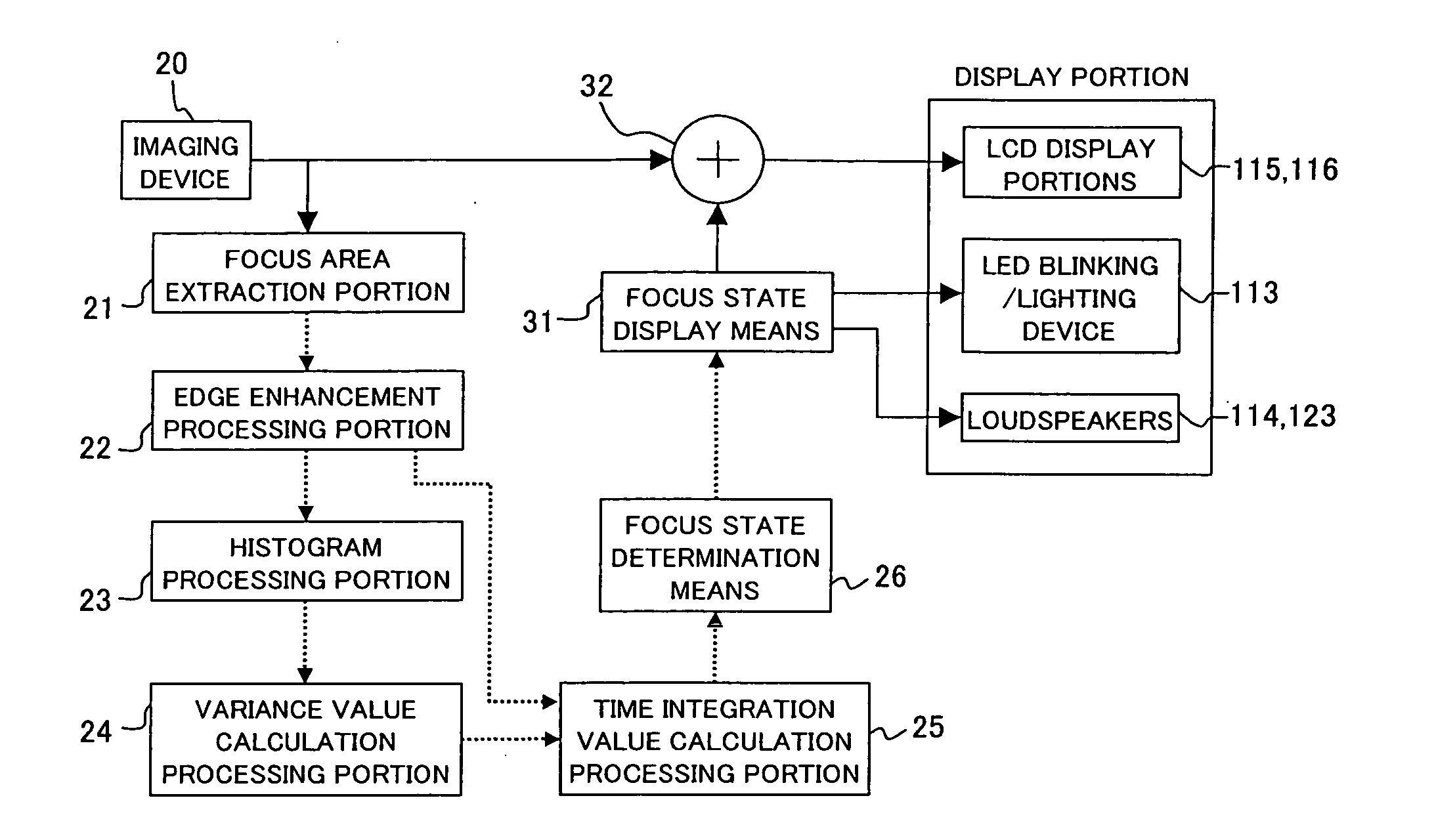
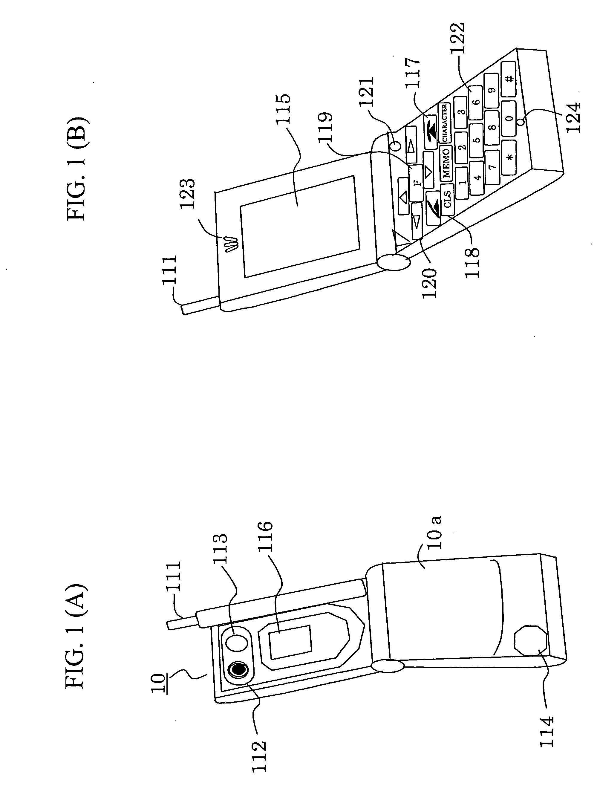
[0068] A first embodiment of the present invention is a camera-equipped portable telephone / PHS (Personal Handy-Phone System) comprising a focus state display apparatus (hereafter simply abbreviated as “portable telephone” so as to simplify the description). FIG. 1 shows an outward appearance of a camera-equipped portable telephone comprising a focus state display apparatus. FIG. 1(A) shows a rear perspective view of the portable telephone of the present embodiment, and FIG. 1(B) shows a front perspective view thereof. FIG. 14 shows a functional block diagram indicating an example of a schematic constitution of the portable telephone according to the present embodiment.

[0069] In FIG. 1, a camera-equipped portable telephone 10 comprises a body portion 10a and an antenna 111 for performing radio communication. The back face of the body portion 10a comprises a camera 112 (imaging means) for photographing an image, an LED (light emitting diode) 113 (light emitting means) for notifying a...

second embodiment

[0122] In the present embodiment, since the constitution of the focus state display apparatus and the portable telephone 10 provided therewith is the same as in the first embodiment shown in FIGS. 1 and 2, description thereof is omitted. The first embodiment is constituted such that the focus state is displayed on the display screens of the LCD display portions 115 and 116 as shown in FIGS. 5 to 11. By contrast, the second embodiment is characterized in that, instead of or in addition to the display on the LCD display portions 115 and 116, the focus state is notified to the user by blinking or lighting the LED 113 disposed in the portable telephone 10 by a predetermined method.

[0123] As a manner for blinking the aforementioned LED 113 by a predetermined method, for example, in FIG. 2, the focus state display means 31 can be constituted such that it calculates a value obtained by dividing a predetermined value by the value of the focus state at all times and blinks the LED 113 using...

third embodiment

[0125] In the present embodiment, since the constitution of the focus state display apparatus and the portable telephone 10 provided therewith is the same as in the first embodiment shown in FIGS. 1 and 2, description thereof is omitted. The first embodiment is constituted such that the focus state is displayed on display screens, namely, the LCD display portions 115 and 116 as shown in FIGS. 5 to 11. By contrast, the second embodiment is characterized in that, instead of or in addition to the display on the LCD display portions 115 and 116, the focus state is notified to the user by causing the loudspeaker 114 or 123 disposed in the portable telephone 10 to produce a predetermined sound.

[0126] As a manner for causing the aforementioned loudspeaker 114 or 123 to produce the predetermined sound, for example, in FIG. 2, the focus state display means 31 can be constituted such that it calculates a value obtained by dividing a predetermined value by the value of the focus state at all ...


PUM


Abstract

A focus state display apparatus comprising focus area extraction means for extracting the image signals of a predetermined area from photographed image signals, edge enhancement processing means for enhancing the edge of the extracted image signals, time integration value calculation means for calculating an integration value of the edge-enhanced image signals in a certain period of time, focus state determination means for determining the focus state of the photographed image signals on the basis of the calculated integration value, and focus state display means for displaying the determined focus state. A user is capable of readily determining the focus state of a camera and confirming and adjusting the focus thereof with accuracy even in a display apparatus of a camera-equipped portable terminal device, where the size and resolution thereof are limited.

Description

TECHNICAL FIELD [0001] The present invention relates to an apparatus for displaying the focus state of a camera and a display method thereof, especially to a technique for displaying the focus state of a small portable camera and a fixed-focus camera disposed in a camera-equipped portable terminal device, such as a portable telephone equipped with an imaging function. BACKGROUND ART [0002] In recent years, with the development of image sensors having small size and low power consumption, portable devices with a built-in camera, such as PDAs (Personal Digital Assistants), portable telephones, and portable PCs (personal computers) have been in widespread use. [0003] These portable devices are capable of photographing images and printed materials instead of taking notes, for example, using a camera such as a built-in CCD camera. Also, they are capable of storing such photographed images in the portable devices and transmitting the photographed images to other portable devices and PCs t...

Claims


Application Information

Patent Timeline
IPC IPC(8): H04N5/228G03B13/36G02B7/28G06V30/224G02B7/36G03B13/32G03B17/18G06V30/10H04N5/225H04N5/232
CPCG03B13/32G03B17/18G03B29/00H04N5/142H04N5/23212H04N5/23293H04N2007/145G06V30/10G06V30/1452G06V30/1456G06V30/127H04N23/675H04N23/673H04N23/631H04N23/635
Inventor HAGINO, YOSHIO
Owner SHARP KK
Why Eureka
Try Eureka