Simultaneous phase shifting module for use in interferometry

a phase shifting module and simultaneous phase technology, applied in the field of interferometry, can solve the problems of measurement errors, insufficient single interferogram to obtain the accuracy required for many applications, and inability to effectively use temporal methods

Active Publication Date: 2006-07-06
TROLOGY
View PDF6 Cites 41 Cited by
  • Summary
  • Abstract
  • Description
  • Claims
  • Application Information

AI Technical Summary

Problems solved by technology

A single interferogram is usually insufficient to obtain the accuracy required for many applications.
However, in practice, these temporal methods cannot be used effectively in the presence of relatively fast changing environmental conditions (such as vibrations, air turbulences, etc), or when the object under test cannot be stabilized (i.e. vibrating), or when the object under test is in motion.
For example, problems can arise because the interferometer typically acquires three to twelve frames (images) or phase shifted interferograms, serially in time, (typically spaced 30 ms apart for standard video), and during this acquisition time (for three to twelve frames), any vibration that occurs between the test and reference object often causes measurement errors.
However, as discussed below in further detail, such known methods have disadvantages, including dissimilar beam paths attributable to different path distances and/or different optical elements.
This system relates to the use of test and reference beams that are mutually orthogonally polarized; however, the system is substantially asymmetric.
As such, the system can be difficult to align and a constant magnification in all three beam paths difficult to maintai

Method used


Image

  • Simultaneous phase shifting module for use in interferometry
  • Simultaneous phase shifting module for use in interferometry
  • Simultaneous phase shifting module for use in interferometry

Examples


Embodiment Construction

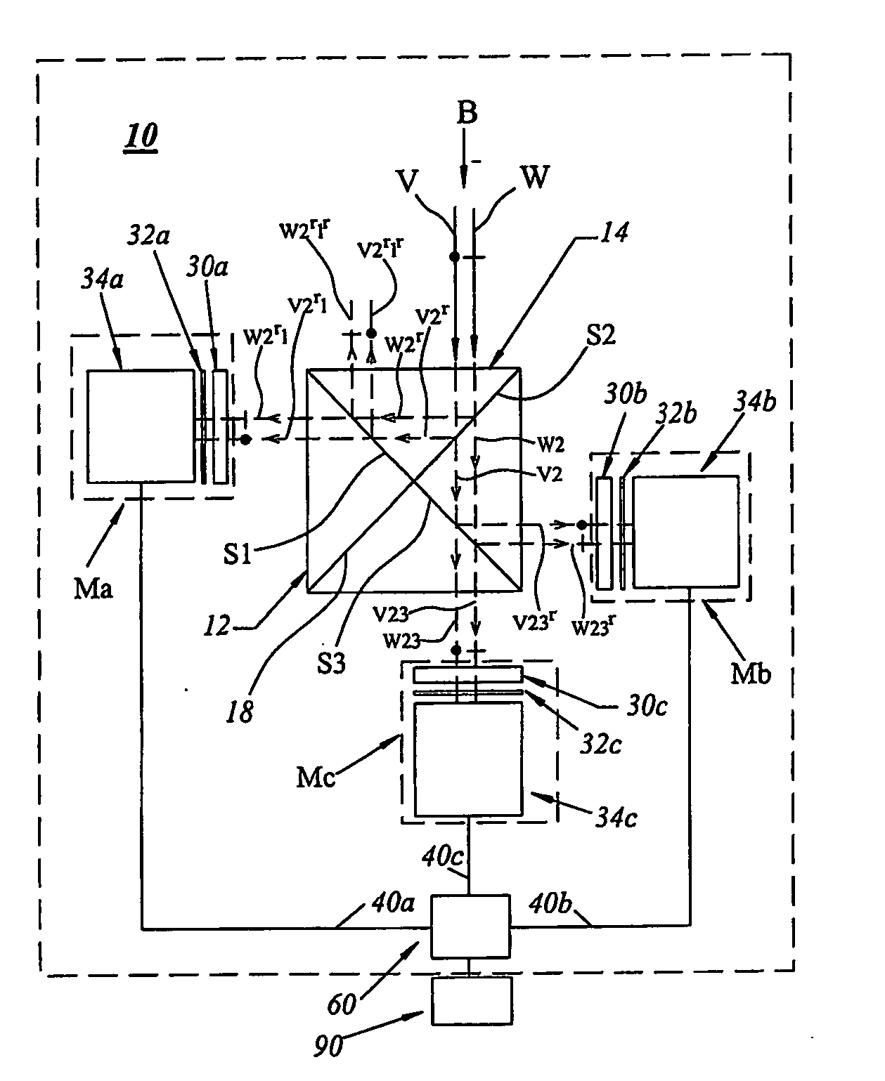
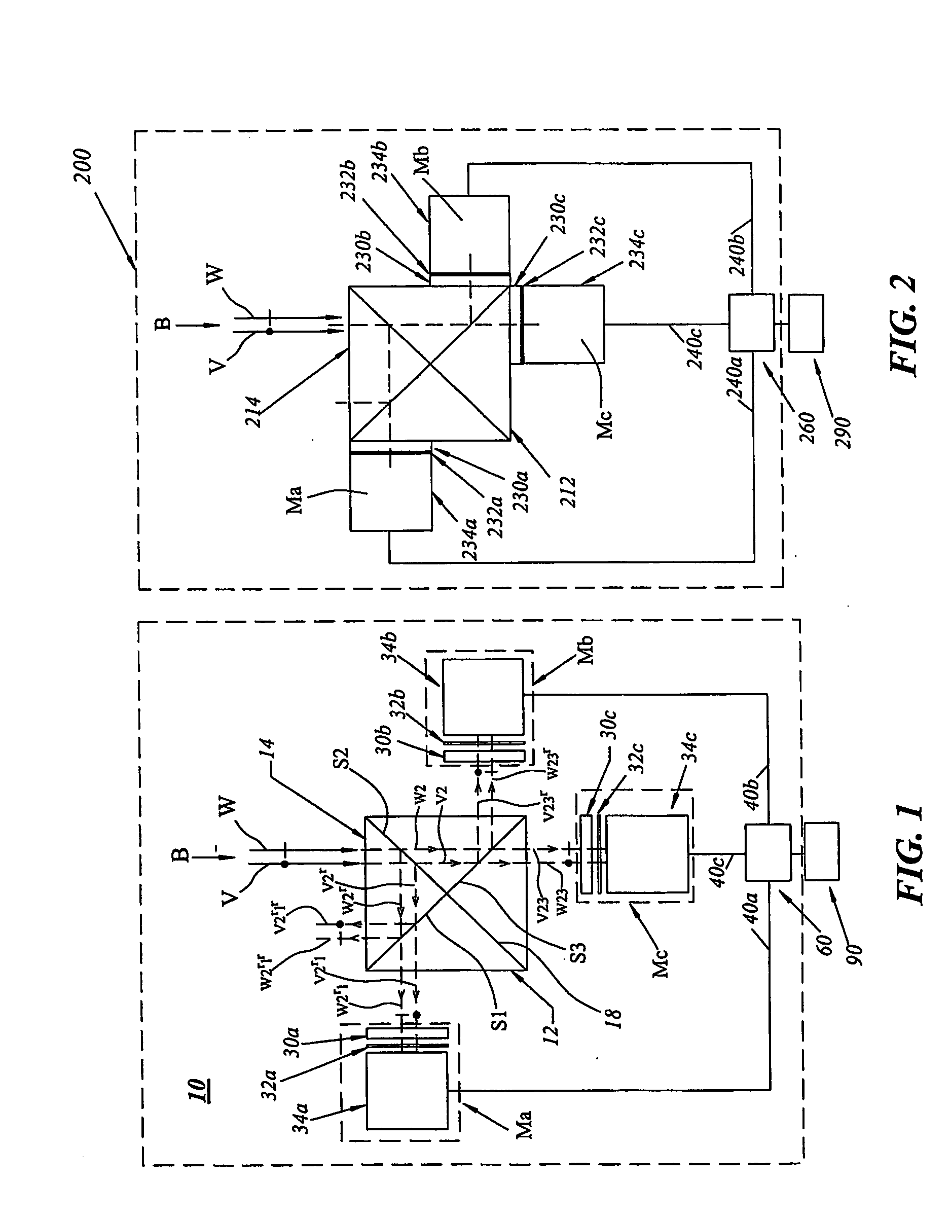
[0031]FIG. 1 illustrates a simultaneous phase-shifting assembly 10 in accordance with an embodiment of the present invention. The assembly 10 is used as a back-end of an interferometric system that generates simultaneously phase-shifted interferograms, as used in compiling 3-D surface profiles of an object under test. The assembly 10 may be used with any front-end assembly that provides superimposed or overlapping reference and test beams with mutually orthogonal linear states of polarization, including those assemblies described in a co-pending U.S. patent application entitled “An Interferometric System With Reduced Vibration Sensitivity and Related Method,” (Attorney Docket No. T535-51537.PCT), the contents of which are incorporated herein by reference. The front-end assembly of the Fizeau-type configuration described therein may be particularly suited in certain conditions for use with the back-end assembly 10 of the instant invention. However, a front-end assembly having a Twyma...


PUM


Abstract

A back-end assembly for use with a front-end assembly in acquiring phase-shifted interferograms having a plurality of imaging modules (Ma, Mb, Mc). Each module (Ma, Mb, Mc) has a quarter wave plate (30a, 30b, 30c), a polarizer (32a, 32b, 32c), and an image sensor (34a, 34b, 34c) so that each polarizer has a different rotation orientation thus acquiring phase-shifted interferograms.

Description

CROSS -REFERENCE TO RELATED APPLICATIONS [0001] This application claims the priority of U.S. Provisional Application Ser. No. 60 / 429,610, filed Nov. 27, 2002, and U.S. Provisional Application Ser. No. 60 / 459,149, filed Mar. 31, 2003, the contents of both which are incorporated herein by reference.FIELD OF THE INVENTION [0002] The present invention relates to interferometry, in particular, interferometry involving the measuring of wavefronts through use of phase-shifted interferograms. Specifically, the present invention relates to interferometers with reduced sensitivity to vibration or other disturbances for use in capturing data from stationary objects and moving objects. BACKGROUND OF INVENTION [0003] Interferometers have been known and used for a long time. Interferometry is a widely used method for measuring surface profiles (often to nano-meter resolutions) and other physical properties of materials, gases and liquids. There are many types of interferometers, characterized by ...

Claims


Application Information

Patent Timeline
IPC IPC(8): G01B9/02
CPCG01B9/02G01B9/02081G01B2290/45G01B2290/70
Inventor SZWAYKOWSKI, PIOTRCASTONGUAY, RAYMONDJBUSHROE, FREDERICKN
Owner TROLOGY
Why Eureka
Try Eureka