Multi-mode signal modification circuit with common mode bypass

a signal modification circuit and common mode technology, applied in the direction of frequency-division multiplex, electric controllers, instruments, etc., can solve the problems of inability to convey both differential mode and common mode signals, cable assemblies that include active amplification components, and disadvantages of conventional passive equalization circuits

Inactive Publication Date: 2006-07-06
TE CONNECTIVITY CORP
View PDF6 Cites 13 Cited by
  • Summary
  • Abstract
  • Description
  • Claims
  • Application Information

AI Technical Summary

Problems solved by technology

However, conventional passive equalization circuits have experienced certain disadvantages.
Hence, cable assemblies that include active amplification components heretofore, were unable to convey both differential mode and common mode signals since the amplifiers blocked any common mode signal component provided on the input lines.

Method used


Image

  • Multi-mode signal modification circuit with common mode bypass
  • Multi-mode signal modification circuit with common mode bypass
  • Multi-mode signal modification circuit with common mode bypass

Examples


Embodiment Construction

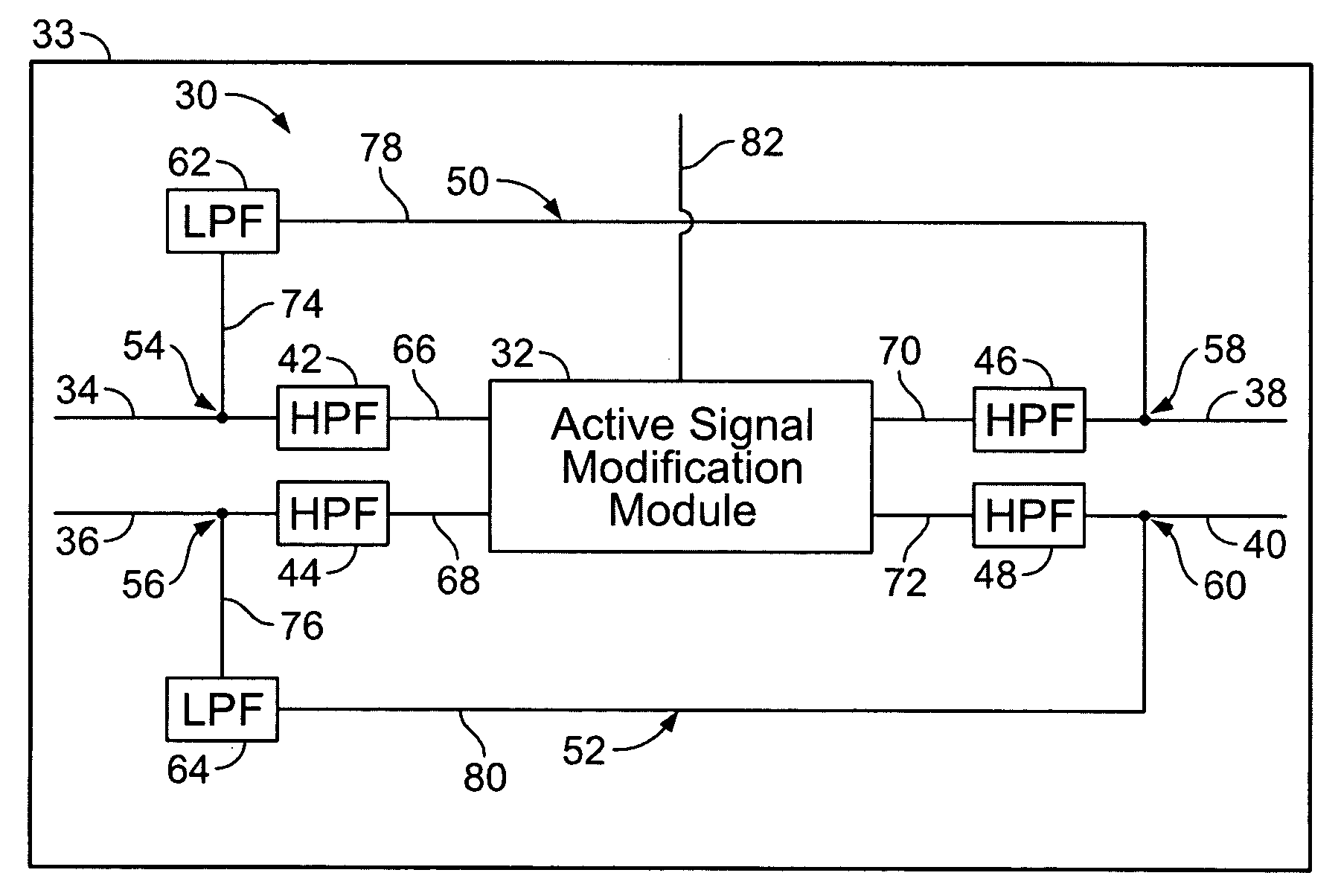
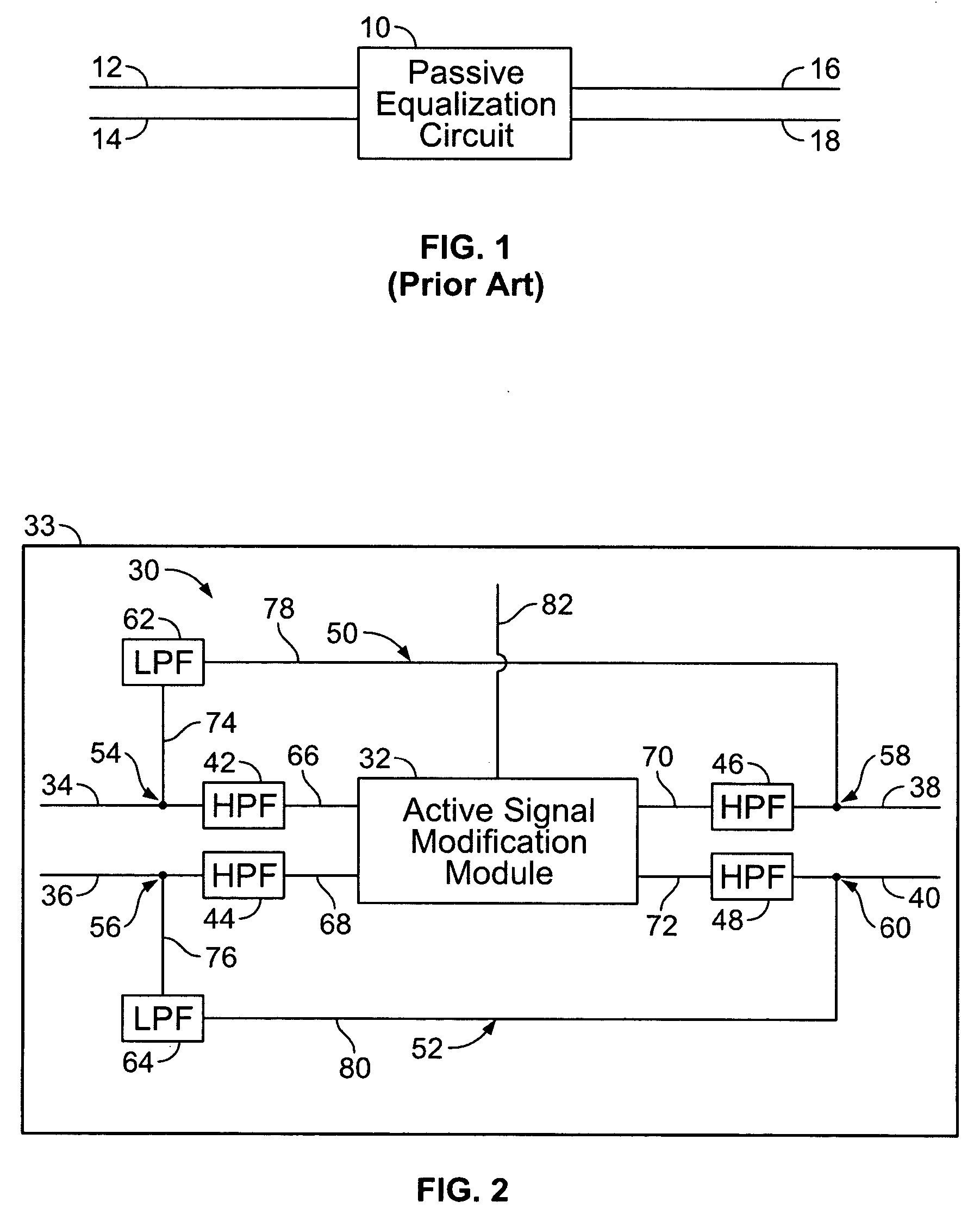
[0012]FIG. 2 illustrates an active bypass circuit 30 formed in accordance with an embodiment of the invention and may be used in a variety of applications. By way of example only, the active bypass circuit 30 may be joined to a transmission line or cable assembly 31 that is utilized to convey one or more of data signals, voice signals, power signals and the like. The cable assembly 31 may have any of several lengths, such as 10 meters, 25 meters, 50 meters and the like. As the length of the cable assembly 31 varies, the active bypass circuit 30 is adjusted accordingly to account for and correct changes in the electrical characteristics of the signals conveyed to and from the active bypass circuit 30. Examples of such electrical characteristics may include jitter, skew, attenuation, cross-talk and the like.

[0013] The active bypass circuit 30 includes an active signal modification module 32 that is joined with input lines 34 and 36 and with output lines 38 and 40. The active bypass c...


PUM


Abstract

A signal modification circuit is provided for use with multi-mode formatted data in accordance with a common mode component and a high frequency component formatted in accordance with a differential mode. The circuit includes an active module that modifies the high frequency component to generate a modified and enhanced high frequency component at an output thereof. A bypass line interconnects the inputs and outputs of the active module to bypass the active module. A low pass filter is provided along the bypass line blocking passage of the high frequency component along the bypass line.

Description

BACKGROUND OF THE INVENTION [0001] The present invention generally related to an active signal modification circuit with a common mode bypass for use with multi-mode signals conveyed within a combination signal of low frequency and high frequency components. [0002] In the past, passive signal conditioning systems have been proposed for use with cable assemblies that convey data signals, power, speech signals and the like. Existing passive signal conditioning systems typically operate with two signal lines, along which a passive equalization circuit is provided. FIG. 1 illustrates an exemplary conventional system having a passive equalization circuit 10 connected with two input lines 12 and 14 and two output lines 16 and 18. The input lines 12 and 14 convey a differential mode signal overlapped with a common mode signal. The term “common mode” as used throughout shall refer to a signal conveyed over one or more input lines, where the signal changes level on each input line at substan...

Claims


Application Information

Patent Timeline
Patent Type & Authority Applications(United States)
IPC IPC(8): H04L5/16H02J3/02H04B1/10H04J1/02
CPCH04L5/20H04L25/03878
Inventor VERMEERSCH, DEAN CAMIEL WILLIAMNGUYEN, THINH PHUC
Owner TE CONNECTIVITY CORP
Why Eureka
Try Eureka