Injection molding machine driving device, injection device, and mold clamping device

a technology of injection molding machine and driving device, which is applied in the direction of applications, manufacturing tools, propulsion systems, etc., can solve the problems of screw advance and retreat, electric-motor-type drive apparatus fails to exhibit high-speed performance, high control accuracy, and screw inertia, etc., to achieve the effect of reducing the size of the drive apparatus, increasing the capacity of the linear motor, and large thrust for

Inactive Publication Date: 2006-07-06
SUMITOMO HEAVY IND LTD
View PDF5 Cites 12 Cited by
  • Summary
  • Abstract
  • Description
  • Claims
  • Application Information

AI Technical Summary

Benefits of technology

[0020] In this case, since the movable element and the stationary element constitute the tubular linear motor, the area of a permanent magnet of the movable element can be sufficiently increased by merely a slight increase in a radial dimension. Accordingly, since the capacity of the linear motor can be increased, the linear motor can generate a large thrust force and can provide short-cycled continuous drive. As a result, the drive apparatus can be mounted in a high-load mechanical apparatus, such as an injection molding machine.
[0021] Since the second drive section is disposed such that at least a portion of the second drive

Problems solved by technology

By contrast, in the electric-motor-type drive apparatus, the metering motor for rotating the screw cannot be disposed on the rotational axis of the screw, so that the moment of inertia cannot be reduced.
Accordingly, the electric-motor-type drive apparatus fails to exhibit high-speed performance, high responsiveness, and high control accuracy.
Supply of predetermined current to the stationary element causes the movable element to advance and retreat, thereby causing the screw to advance and retreat.
The drive apparatus of either type fails to exhibit high-speed performance, high responsiveness, and high control accuracy.
However, since the linear motor does not have a decelerating mechanism, use of the linear motor as the conventional drive apparatus; i.e., use of the linear motor as a drive apparatus for an injection molding machine, which is a high-load mechanical apparatus, requires an increase in the cap

Method used


Image

  • Injection molding machine driving device, injection device, and mold clamping device
  • Injection molding machine driving device, injection device, and mold clamping device
  • Injection molding machine driving device, injection device, and mold clamping device

Examples


first embodiment

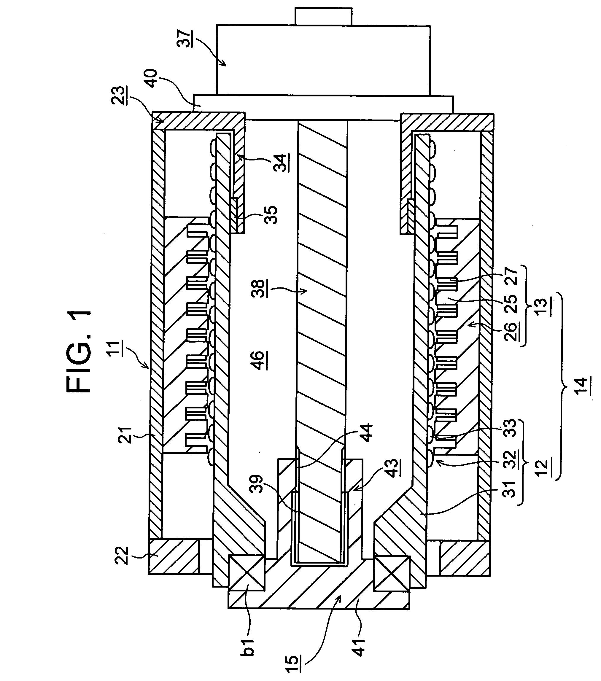
[0043]FIG. 1 is a sectional view of a drive apparatus according to the present invention. In this case, there is described a drive apparatus mounted in a molding machine, which is one type of mechanical apparatus; for example, an injection molding machine.

[0044] In the drawing, reference numeral 11 denotes a cylindrical housing; reference numeral 12 denotes a cylindrical, movable element disposed within the housing 11 in a manner capable of axially advancing and retreating (moving in the left-right direction in the drawing); reference numeral 13 denotes a cylindrical stationary element attached to the inner circumferential surface of the housing 11; and reference numeral 15 denotes a member-to-be-driven, which is disposed in a rotatable relationship to the movable element 12 via a bearing b1 and in a manner capable of advancing and retreating together with the movable element 12. An unillustrated movable member is disposed ahead (leftward in the drawing) of the member-to-be-driven 1...

second embodiment

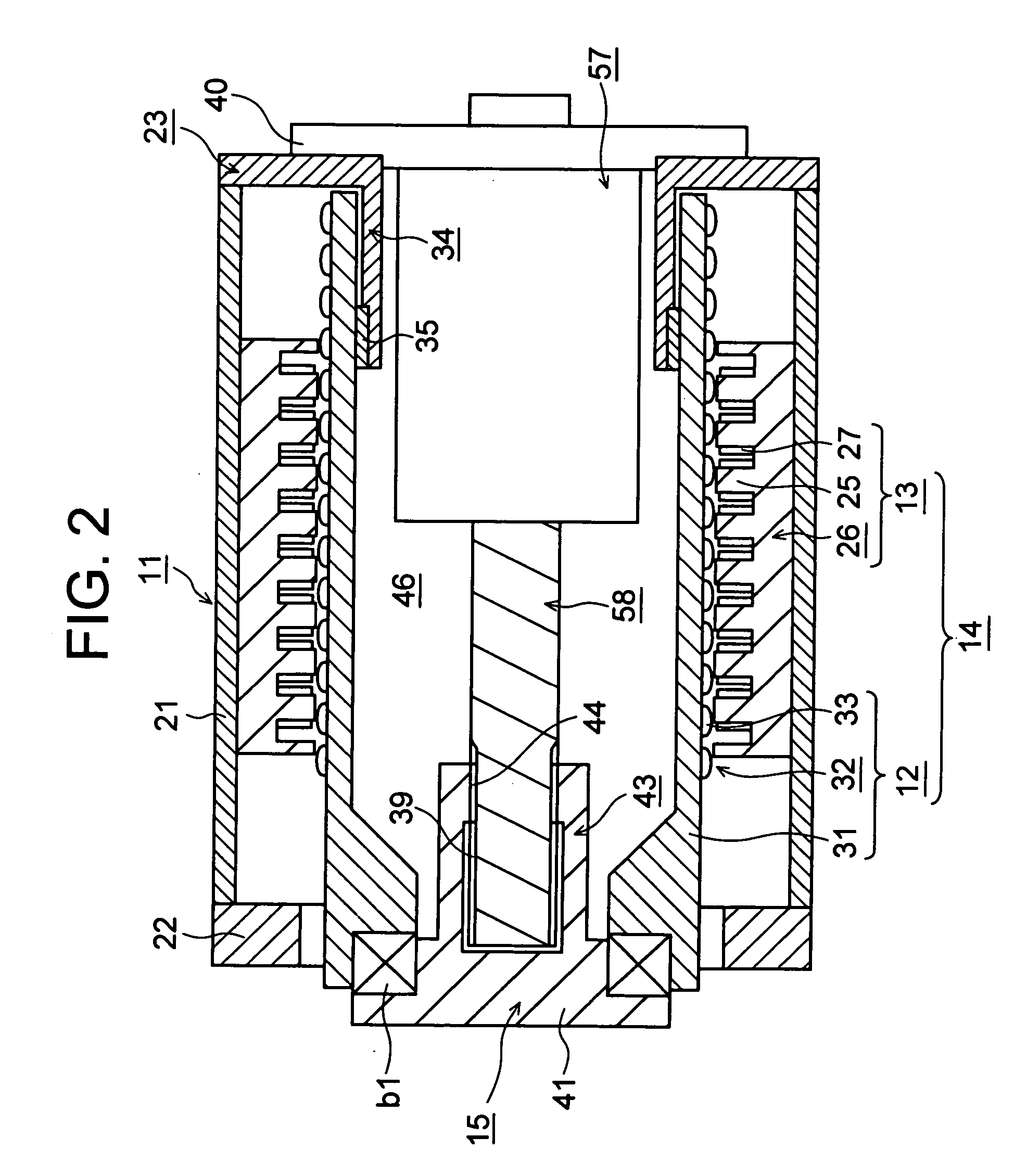
[0062]FIG. 2 is a sectional view of a drive apparatus according to the present invention.

[0063] In this case, in order to rotate the member-to-be-driven 15, an electric motor 57, such as a servomotor, which serves as a rotary, second drive section, is attached to the rear end face (right end face in the drawing) of the rear plate 23 via the flange 40, which serves as a mounting portion, and projects frontward (leftward in the drawing). The motor 57 is of an inner rotor type and includes an unillustrated stator and an unillustrated rotor, which is rotatably disposed radially inward of the stator. The motor 57 is driven through supply of predetermined current; for example, U-phase, V-phase, and W-phase currents, to the stator, whereby the member-to-be-driven 15 can be rotated, and the movable member can be rotated.

[0064] To achieve the above operation, an output shaft 58 of the motor 57 is disposed at the center within the space 46 and extends frontward. The splines 39 are formed on ...

third embodiment

[0068]FIG. 3 is a sectional view of a drive apparatus according to the present invention.

[0069] In this case, the movable element 12 and the member-to-be-driven 15 are fixed to each other and are disposed in a rotatable relationship to the housing 11 and in a manner capable of advancing and retreating (moving in the left-right direction in the drawing) in relation to the housing 11. In order to allow such movements, a support member 55, such as a linear ball bearing, is disposed on the outer circumferential surface of the front end (left end in the drawing) of the support portion 34 so as to support the movable member 12 such that the movable member 12 is movable in the axial direction and in the circumferential direction. Also, an unillustrated support member, such as a linear ball bearing, is disposed on the inner circumferential surface of the front plate 22 so as to support the movable element 12 such that the movable member 12 is movable in the axial direction and in the circum...


PUM

PropertyMeasurementUnit
Forceaaaaaaaaaa
Electrical conductivityaaaaaaaaaa

Abstract

An object is to provide a drive apparatus for an injection molding machine which can generate a large thrust force and can provide short-cycled continuous drive. The drive apparatus includes a housing (11); a tubular linear motor (14) including a movable element (12) disposed within the housing (11) in a manner capable of advancing and retreating, and a stationary element (13) attached to the housing (11), the linear motor (14) serving as a first drive section; a member-to-be-driven (15) caused to advance and retreat together with the movable element (12); and a second drive section attached to the housing (11) and disposed such that at least a portion of the second drive section overlaps the linear motor (14) along the axial direction. By merely a slight increase in a radial dimension, the area of a permanent magnet (23) of the movable element (12) can be sufficiently increased, and the capacity of the linear motor (14) can be increased.

Description

TECHNICAL FIELD [0001] The present invention relates to a drive apparatus for an injection molding machine, an injection apparatus, and a mold clamping apparatus. BACKGROUND ART [0002] Conventionally, hydraulic-type and electric-motor-type drive apparatus have been used for generating thrust force in various mechanical apparatus. [0003] In a molding machine, which is one type of mechanical apparatus; for example, an injection molding machine, a resin is melted within a heating cylinder through application of heat; the thus-molten resin is injected under high pressure into a cavity of a mold apparatus so as to fill the cavity; and the resin within the cavity is cooled to set, thereby yielding a molded article. [0004] The injection molding machine has a mold apparatus, a mold claming apparatus, and an injection apparatus. The mold apparatus includes a stationary mold and a movable mold. The mold clamping apparatus includes a stationary platen to which the stationary mold is attached, ...

Claims


Application Information

Patent Timeline
IPC IPC(8): B29C45/20B29C45/50B29C45/66H02K7/14H02K16/00H02K41/03
CPCB29C45/66B29C2045/1793H02K7/14H02K21/222H02K41/031H02K2201/18H02K16/00B29C45/17B29C45/50
Inventor KONNO, TAKESHI
Owner SUMITOMO HEAVY IND LTD
Why Eureka
Try Eureka