Surgical nail

Active Publication Date: 2006-07-06
DEPUY SYNTHES PROD INC
View PDF70 Cites 38 Cited by
  • Summary
  • Abstract
  • Description
  • Claims
  • Application Information

AI Technical Summary

Benefits of technology

[0020] In the case of a special execution, the transverse bore expands towards the surface of the nail, preferably in the form of a tapered section. The ad

Problems solved by technology

In both cases, a certain aiming inaccuracy is unavoidable because the tip of the screw cannot be aligned exactly coaxially with the central axis of the transverse bore, and instead deviates therefrom by a certain amount.
While some play or clearance is essential to guarantee the usefulness of the locking for surgeons, in the case of some indications (e.g. i

Method used


Image

  • Surgical nail
  • Surgical nail
  • Surgical nail

Examples


Embodiment Construction

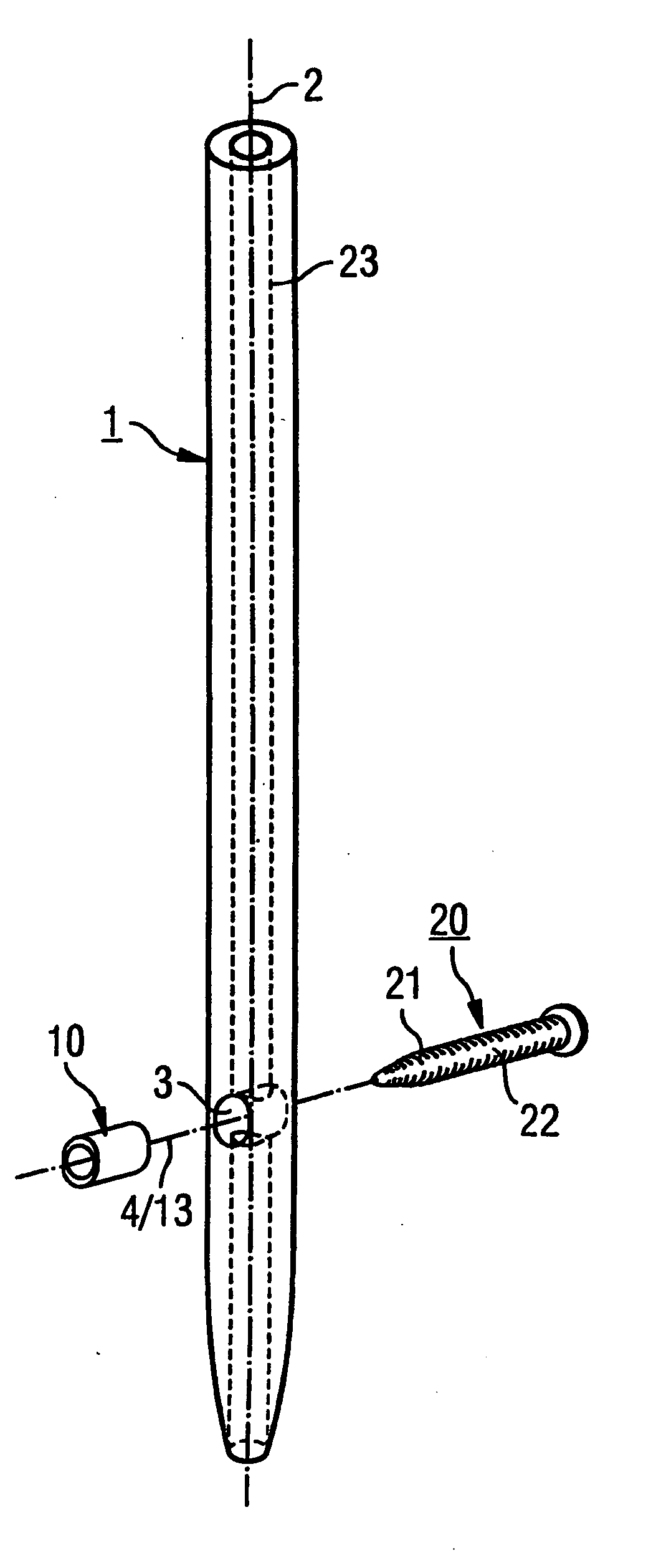
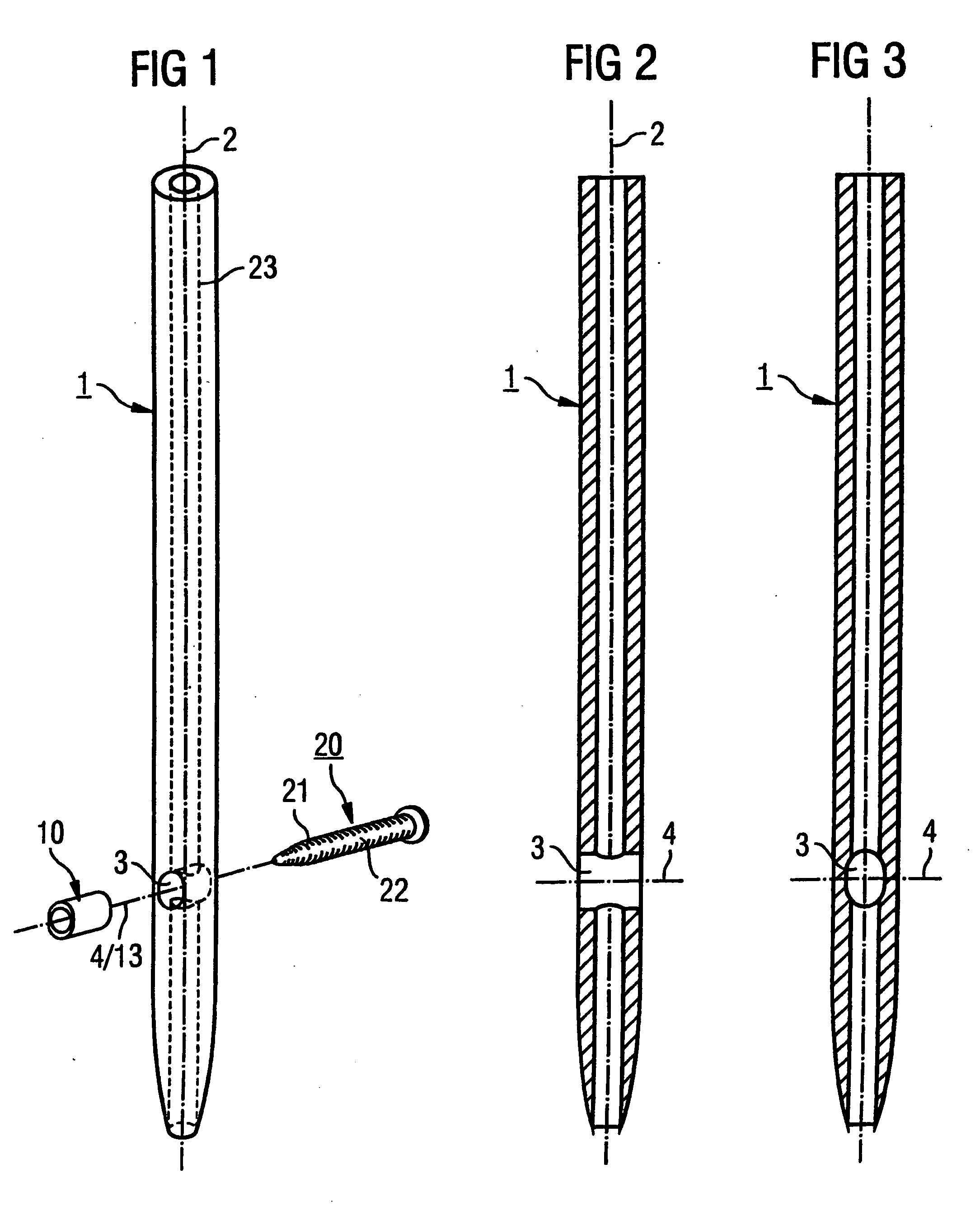
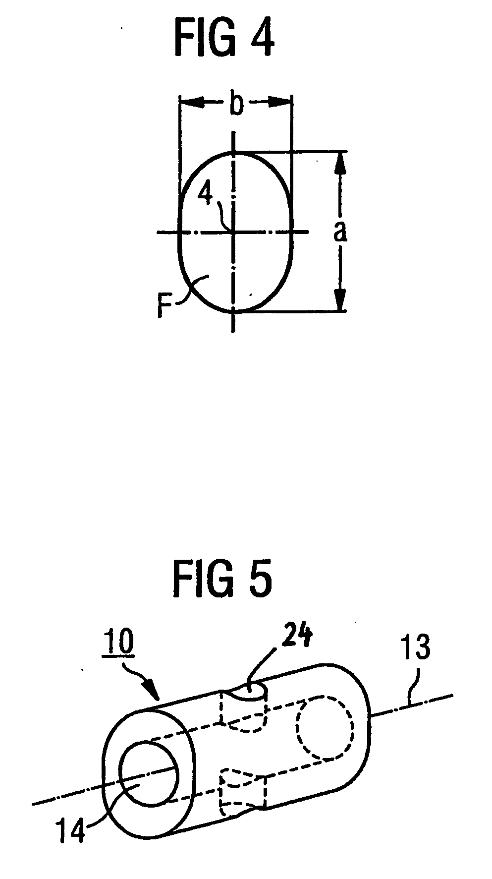
[0029] The surgical nail 1 illustrated in FIGS. 1-3 is an intramedullary nail for hollow bones with a central axis 2, that is made from a metal or a metal alloy, i.e. a material with relatively high strength (tensile strength Fz, compression strength Fd and modulus of elasticity E). The nail 1 has a transverse bore 3, having a transverse axis 4 and extending as a slotted hole with the cross-section F towards the central axis 2. As illustrated in FIG. 4, the transverse bore 3 has a cross-section F, that has its maximum length a in the direction of the central axis 2 and its maximum width b perpendicular to the length a. The nail can have further transverse bores (circular or oval), which are not illustrated.

[0030] As illustrated in FIG. 1, an insert 10 is provided to be introduced into the transverse bore 3. The dimensions of the insert 10 are congruent with that of the transverse bore 3 or are so chosen that its insertion results in a press fit, thus preventing the insert from fall...


PUM


Abstract

The invention relates to a surgical nail in the form of an intramedullary nail with a central axis made from a material M with a tensile strength Fz, compressive strength Fd, density ρ2 and modulus of elasticity E. Said nail has a transverse bore extending transversely to the central axis and having a cross-sectional profile F and a transverse axis, the cross-sectional profile F having a maximum length a that runs in the direction of the central axis and a maximum width b that runs perpendicular to the length. An insert with the longitudinal axis, made from material m and having a modulus of elasticity e that is smaller than the modulus of elasticity E of material M, can be introduced into the transverse bore. The insert also has a length L that runs in the direction of its longitudinal axis and satisfies the condition L>0.2 D.

Description

RELATED APPLICATION DATA [0001] The present application is a continuation of the U.S. National Stage designation of co-pending International Patent Application No. PCT / CH2003 / 000376, filed Jun. 12, 2003, the entire content of which is expressly incorporated herein by reference thereto.FIELD OF THE INVENTION [0002] The invention relates to a surgical nail and, more particularly, to an intramedullary nail having a longitudinal axis and an insert for insertion into a transverse bore through the intramedullary nail. BACKGROUND OF THE INVENTION [0003] The locking of intramedullary nails is known in the art. The introduction of locking screws or locking bolts (hereinafter referred to collectively as “locking screws”) into the transverse bores of a intramedullary nail is carried out either with the aid of an imaging process (X-ray control) or a relatively complicated aiming device. In both cases, a certain aiming inaccuracy is unavoidable because the tip of the screw cannot be aligned exac...

Claims


Application Information

Patent Timeline
IPC IPC(8): A61B17/56A61B17/00A61B17/72
CPCA61B17/72A61B17/7241A61B2017/00004
Inventor SCHLIENGER, ANDREBUETTLER, MARKUSSENN, PETER
Owner DEPUY SYNTHES PROD INC
Why Eureka
Try Eureka