Corrective element for the articulation between the femur and the pelvis

Inactive Publication Date: 2006-07-06
ROMAGNOLI SERGIO
View PDF33 Cites 22 Cited by
  • Summary
  • Abstract
  • Description
  • Claims
  • Application Information

AI Technical Summary

Benefits of technology

[0004] The aim of the invention is to eliminate the drawbacks noted above, by providing a corrective element for the articulatio

Problems solved by technology

This approach is particularly traumatic, since dislocation of the head of the femur

Method used


Image

  • Corrective element for the articulation between the femur and the pelvis
  • Corrective element for the articulation between the femur and the pelvis
  • Corrective element for the articulation between the femur and the pelvis

Examples


Embodiment Construction

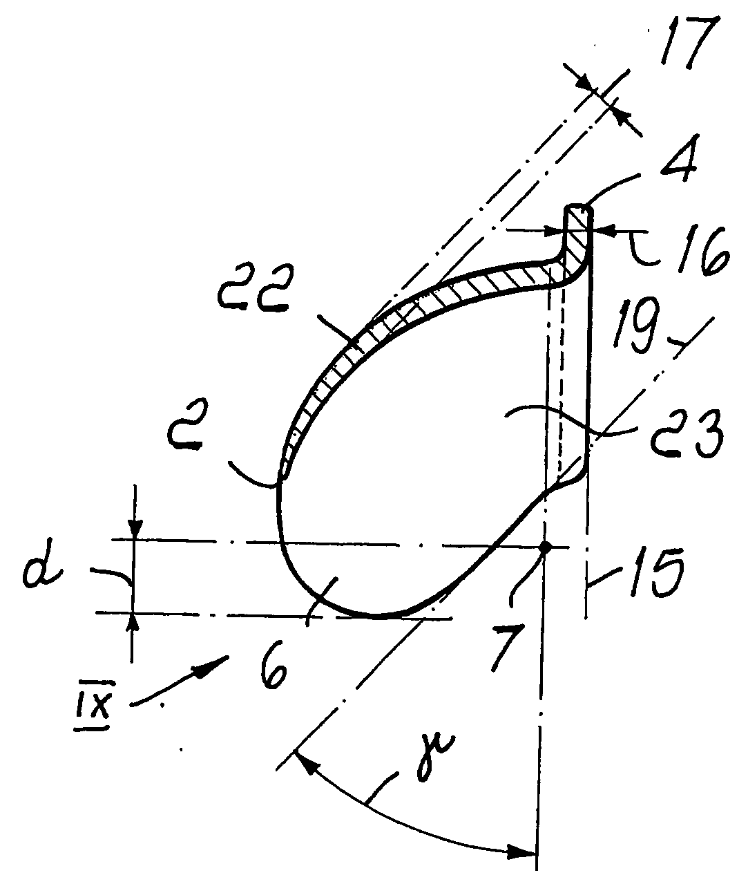
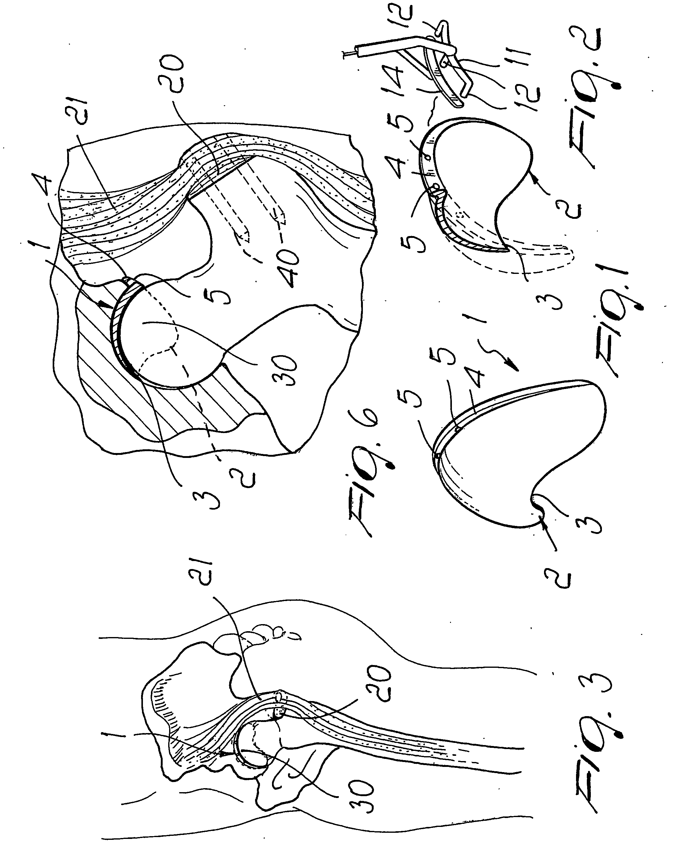
[0022] With reference to the figures, the corrective element for the articulation between the femur and the pelvis, according to the invention, comprises a contoured body 1, which is preferably made of steel and has a shape that approximate a spherical portion.

[0023] The contoured body 1 has a beveled insertion edge 2, in which the thickness decreases to zero, and has, in a central portion, a central recess 3 for the reason explained hereinafter.

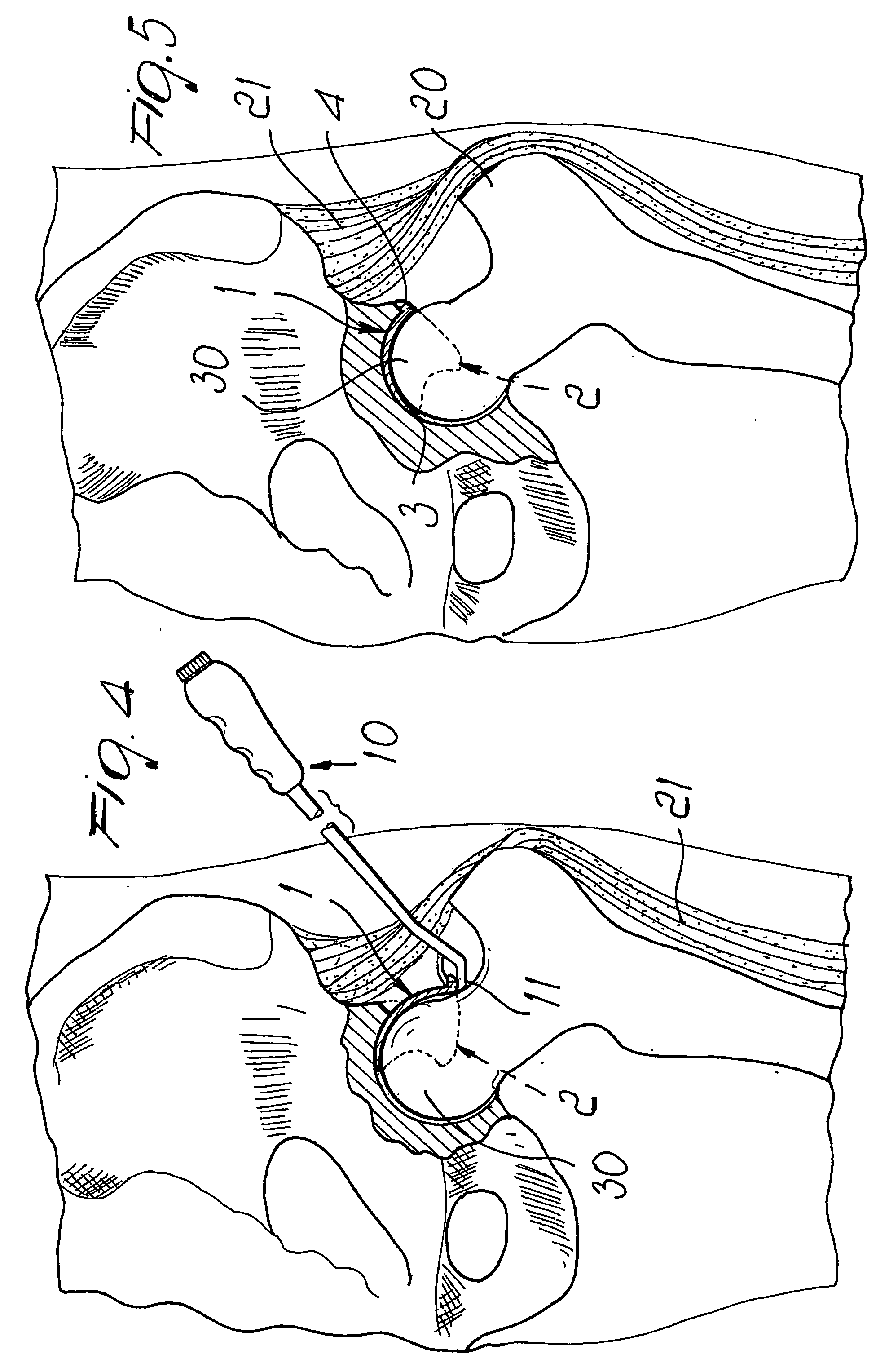
[0024] On the opposite side, the body 1 has a pushing and positioning edge 4, provided with multiple holes 5 for manipulation by means of a suitable instrument or lever 10 that facilitates insertion operations.

[0025] The instrument 10 has a push plate 11 that is provided with coupling pins 12 that enter the holes 5 located on the pushing edge 4, and there is also a complementary jaw 14, which is actuated by a suitable lever mechanism and engages the edge 4 on the opposite side, so as to practically clamp the edge 4 on the instrument 10 in...


PUM


Abstract

A corrective element for the articulation between the femur and the pelvis, comprising a contoured body that can be inserted, without dislocation of the head of the femur, in the iliac acetabular region after incision of the articular capsule; the contoured body has a smooth outer surface that is substantially adapted to the iliac acetabular region and an inner surface that forms a seat for accommodating the femur head.

Description

TECHNICAL FIELD [0001] The present invention relates to a corrective element or implant for the articulation between the femur and the pelvis. BACKGROUND ART [0002] As is known, when problems in the articulation between the femur and the pelvis arise, currently the head of the femur is extracted from the acetabular seat and a prosthesis is inserted, by way of the most disparate technologies, recreating in practice the seat for accommodating the head of the femur. [0003] This approach is particularly traumatic, since dislocation of the head of the femur causes considerable problems and further entails performing long and complex surgery. DISCLOSURE OF THE INVENTION [0004] The aim of the invention is to eliminate the drawbacks noted above, by providing a corrective element for the articulation between the femur and the pelvis that allows to restore correct articulation without having to dislocate the head of the femur. [0005] Within this aim, an object of the invention is to provide a...

Claims


Application Information

Patent Timeline
IPC IPC(8): A61F2/32A61F2/36A61F2/30A61B17/56A61B17/68A61FA61F2/00A61F2/34A61F2/46
CPCA61B17/562A61B17/68A61F2/30721A61F2/30739A61F2/30767A61F2/32A61F2/4603A61F2002/0086A61F2002/30131A61F2002/30245A61F2002/30324A61F2002/30563A61F2002/30578A61F2002/30616A61F2002/30754A61F2002/3093A61F2002/3432A61F2002/3487A61F2002/3491A61F2002/4635A61F2230/0013A61F2230/0071A61F2250/0036A61F2002/349
Inventor ROMAGNOLI, SERGIO
Owner ROMAGNOLI SERGIO
Why Eureka
Try Eureka