Socket engaging tether for electronic devices

a technology of electronic components and sockets, which is applied in the direction of press-button fasteners, traveling carriers, travelling articles, etc., can solve the problems of affecting the surface of the device, affecting the adhesive quality, and all solutions can only affect the attachment method, so as to achieve easy engagement and disengagement, the effect of easy engagemen

Inactive Publication Date: 2006-07-13
MOORE CHRISTOPHER
View PDF36 Cites 12 Cited by
  • Summary
  • Abstract
  • Description
  • Claims
  • Application Information

AI Technical Summary

Benefits of technology

[0015] The present invention provides a means for a user to secure electronic articles to his person through socket based compressive frictional engagement. The disclosed device herein easily engages with electronic devices using already available electronic jacks, sockets, receptacles or other orifices, concavities or extensions-like antennae that are already readily present in or on conventional electronic devices as provided by the manufacturer. The device allows for easy engagement and disengagement to a wide variety of electronic devices without modifications to the device itself or the need for any other component to encase the electronic device being secured.

Problems solved by technology

Until now; however, all solutions can only effect their attachment methodology through some purpose-built attachment point designed into the device itself.
Though useful, this device demonstrates what shall be seen to be a recurring flaw in all preceding designs.
The obvious flaw in this approach is that the item to be secured must possess a suitable “manufactured in” surface or structure to provide the device attachment point for a ring or loop to permit the attachment to the retractable lanyard assembly.
The flaw here is that suitable apertures to accept mechanical screws would need to be drilled by the user or provided by the manufacturer in the basic design when manufactured at increased cost.
The shortcomings of the second method proposed, adhesives, are that they can permanently affect the surface of the device, they tend to be sporadic in the effectivity of their adhesive qualities based on the abilities of the person applying them and, as well, those adhesive qualities are often adversely affected by even moderate temperature fluctuations.
Though this implementation resolves both the problems noted in the examples above, it engenders another more significant negative property: it can only be used on devices which are created to accept it.
As a result, generic interchangeability with other potential devices to be secured would be limited to only those devices of manufacturers adopting the technology, thus severely limiting overall functionality.
Though this method solves some of the issues noted above, it is flawed in that it too is a device specific implementation requiring that the device to be secured be designed from its inception to accommodate the necessary hardware.

Method used


Image

  • Socket engaging tether for electronic devices
  • Socket engaging tether for electronic devices

Examples


Embodiment Construction

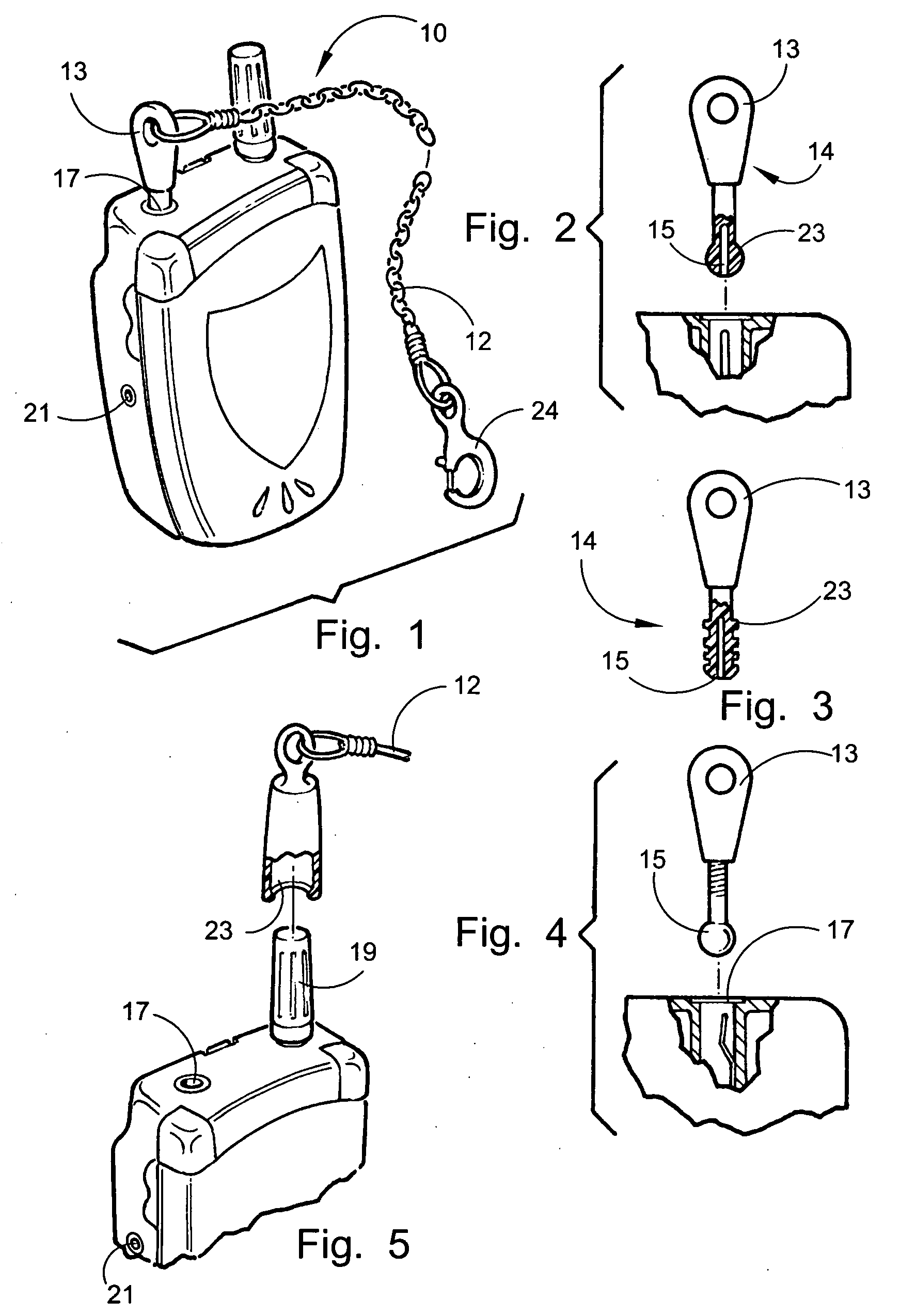
[0029] Referring now to the drawings FIGS. 1-5 which disclose the preferred embodiments of the herein disclosed device, the present invention is defined in the description which follows in reference to the noted plurality of drawings by way of non-limiting examples of embodiments of the present invention in which like reference numerals represent similar parts throughout the several views of the drawings.

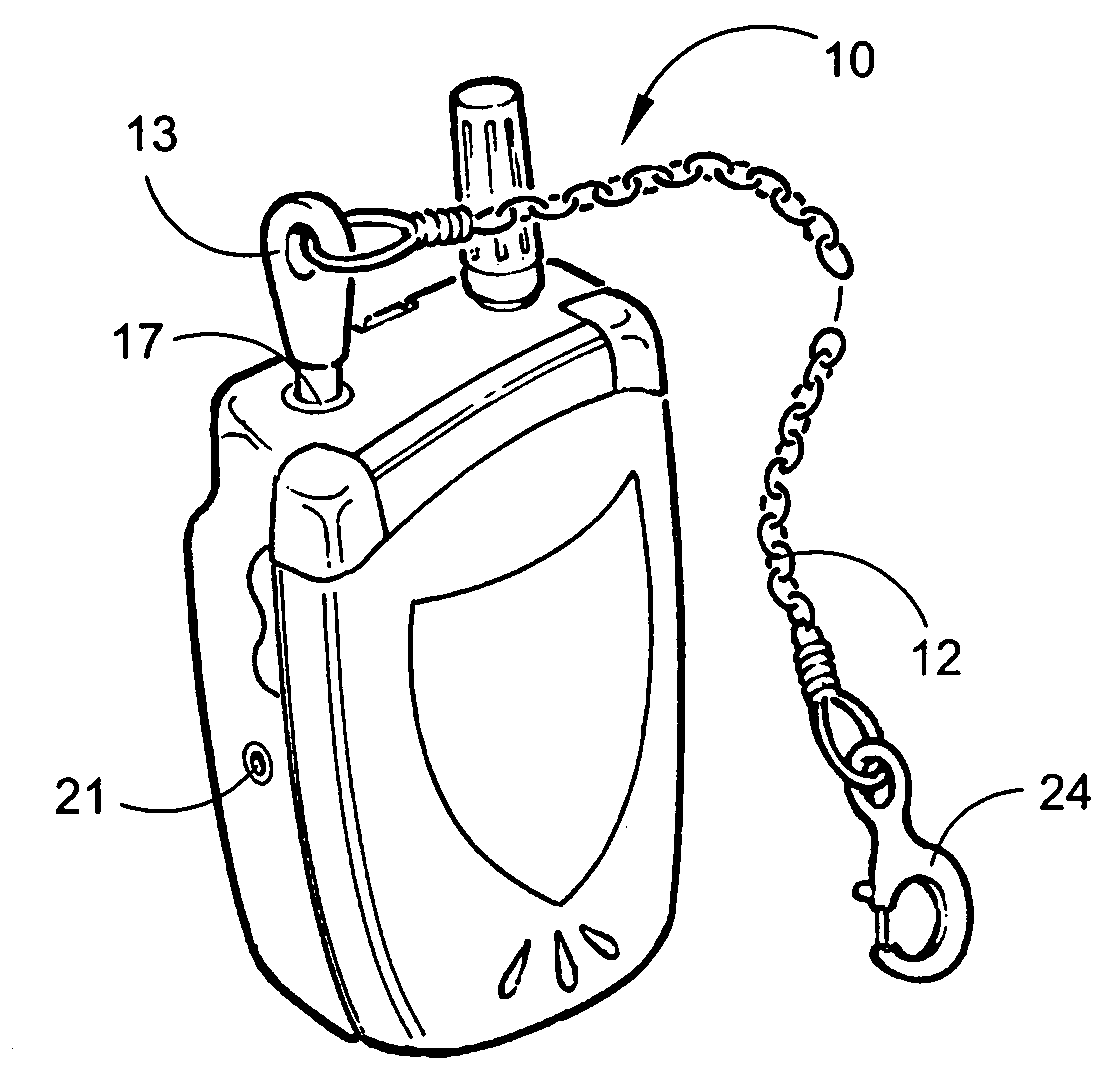
[0030] In FIG. 1 there is depicted an engaged perspective view of the disclosed device 10. The device 10 in this embodiment and all other embodiments feature a tether 12 which may be straight, coiled or spring-loaded. A first end 13 of the plug 14 is protruding from the engagement with a cell phone or other electronic device having a port engageable with the device 10. At the second end 15 of the plug 14 is a preferably non-conductive compressive socket insert adapted for frictional engagement with one of a socket 17 or protruding antenna 19 of any portable electronic device having...


PUM


Abstract

A tether for electronic devices employing a plug having a first end adapted for engagement to a tether and a second end formed on non-conductive material having an exterior surface with an exterior circumference adapted for frictional engagement with the interior circumference of an electrical socket. The second end can be formed of compressible material having an exterior circumference slightly larger than the socket for a biased engagement. An axial void can also be provided to accommodate projections in the socket or to engage an antenna.

Description

FIELD OF THE INVENTION [0001] The apparatus herein disclosed relates to a tethering device for electronic components. More particularly it relates to a device for securing such electronic devices to an individual by employing a non-conductive plug that mechanically engages with electronic components of the device itself. The device includes a plug having a first end for attachment to a tethering assembly or other security mechanism and a second end for attachment through compressive frictional force to a concavity within or an extension upon an electronic or other device. Such an engagement is achieved in all cases without adversely affecting any of the functional electronic characteristics of the device during use. Examples of such devices include but are not limited to cellular phones, pagers, cd players, PDA's, radios, calculators, flashlights, key chains, stun guns and the like which have electronic sockets or antennas engageable by the disclosed device herein. [0002] 1. Backgro...

Claims


Application Information

Patent Timeline
Patent Type & Authority Applications(United States)
IPC IPC(8): A44B21/00A44B99/00
CPCA45F5/00Y10T24/1397Y10T24/312A45F2005/006
Inventor MOORE, CHRISTOPHER G.
Owner MOORE CHRISTOPHER
Why Eureka
Try Eureka