Method, system, controller and computer program product for controlling the flow of a multiphase fluid

a multi-phase fluid and controller technology, applied in the direction of liquid/fluent solid measurement, instruments, borehole/well accessories, etc., can solve problems such as plug flow, and achieve the effect of simple and flexible hardware arrangement and maximum production of multi-phase fluid

Active Publication Date: 2006-07-13
SHELL USA INC
View PDF6 Cites 28 Cited by
  • Summary
  • Abstract
  • Description
  • Claims
  • Application Information

AI Technical Summary

Benefits of technology

[0021] In a particular embodiment of the method an indication of a multiphase flow regime mode is obtained, and the proportionality factor and/or the setpoint of the flow parameter is modified in dependence of the multiphase flow regime. This allows the control system to respond particularly effectively to significant changes in the multiphase flow. The indication of the multiphase flow regime can for example be obtained by monitoring the time derivative of the pressure drop over the restriction, or from an acoustic sensor acoustically coupled to the conduit, or by monitoring a pressure at an upstream position in the conduit such as the riser bottom pressure.
[0022] The control loop described thus far can represent an inner control loop of a more complex control algorithm, including one or more outer control loops as well. An outer control loop differs from the inner control loop in its characteristic control time, which is generally much slower than for the inner control loop. One particular outer control loop can aim to ...

Problems solved by technology

A particular problem in such operations is the occurrence of plug flow.
In an undesirable situation, liquid slugs and gas surges are produced alternatingly through the conduit.
Such an alt...

Method used


Image

  • Method, system, controller and computer program product for controlling the flow of a multiphase fluid
  • Method, system, controller and computer program product for controlling the flow of a multiphase fluid
  • Method, system, controller and computer program product for controlling the flow of a multiphase fluid

Examples


example 1

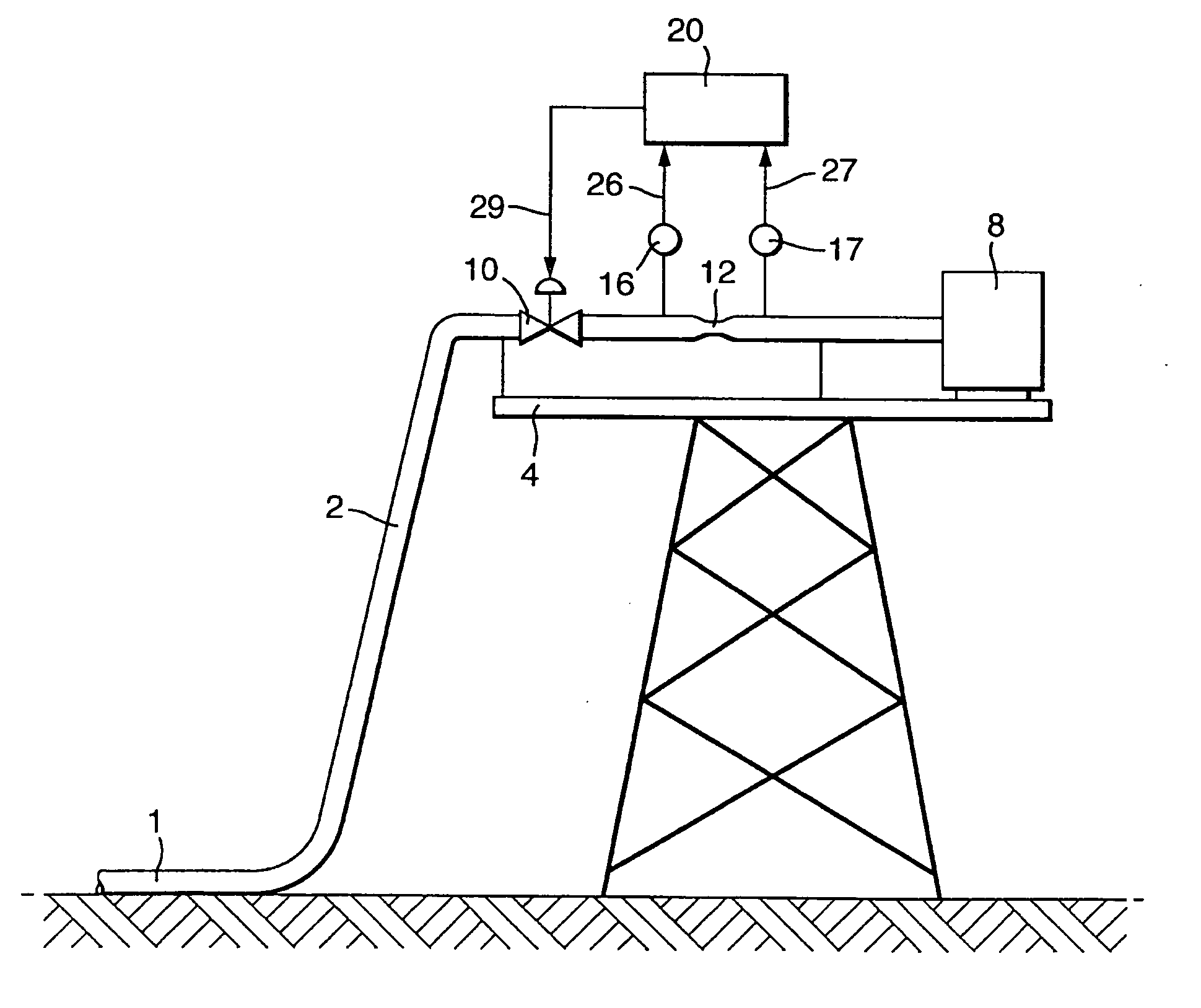
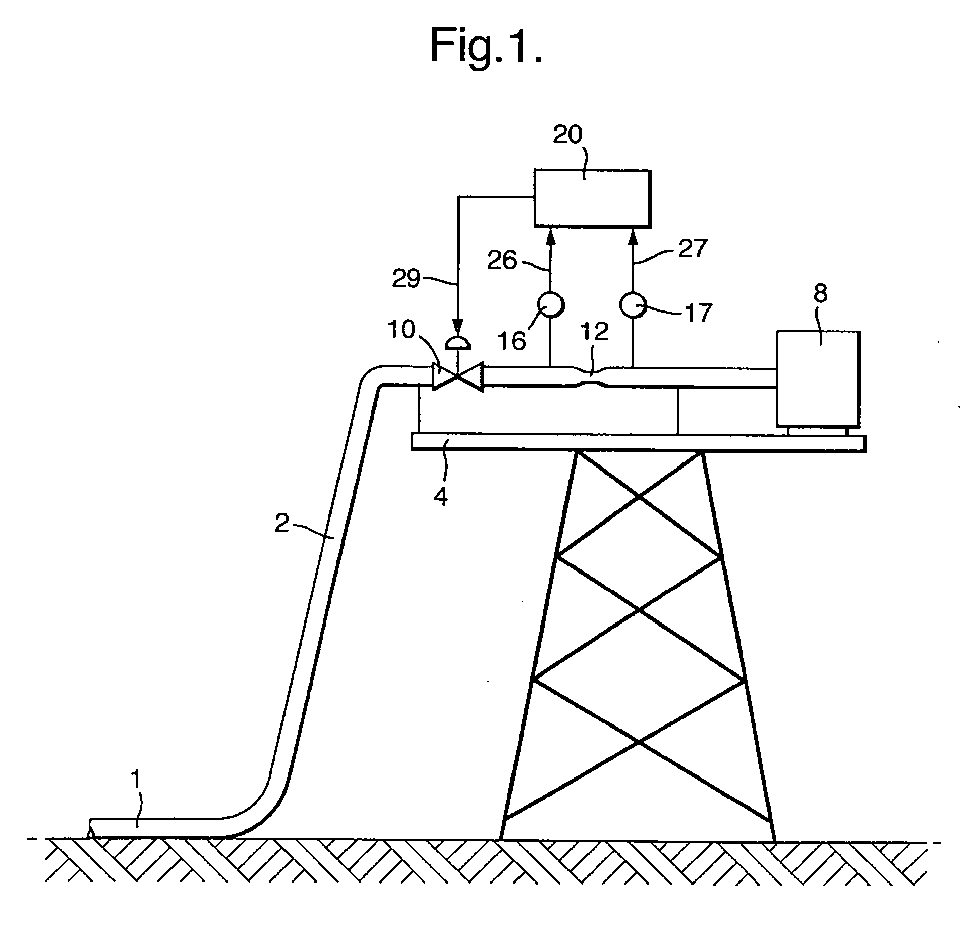
[0050] Consider a subsea pipeline with 0.3038 m inner diameter (12″) producing liquid oil at a flowrate of 270 m3 / hr oil and gas at a flowrate of 300,000 Sm3 / d. The pipeline has a length of 13 km, and the import riser to the production has a height of 190 m. A variable production valve is used as the restriction, and the pressure upstream and downstream of the valve are monitored. The target average pressure upstream of the valve is 23 bara, and the downstream pressure is 20 bara. The gas density at 23 bara is 20.4 kg / m3 and the liquid density is 785 kg / m3. The gas volumetric and mass flow at 23 bara is 555 m3 / hr and 11322 kg / hr, respectively. The liquid volumetric and mass flow at 23 bara is 270 m3 / hr and 211950 kg / hr, respectively. The gas mass fraction x at 23 bara is 0.050709. The total volumetric flow at 23 bara is 825 m3 / hr. The total mass flow at 23 bara is 223272 kg / hr.

[0051] The maximum liquid drain capacity of the downstream equipment is 340 m3 / hr, which equals 266900 kg / ...

example 2

[0072] Consider the same subsea pipeline with the same operating parameters as in Example 1. The volumetric flow rate Q is used as controlled variable, and is determined from monitoring the pressure difference over the variable valve as described hereinbefore. Also, the time derivative of the pressure difference is determined and evaluated, so as to determine the mode of multiphase flow. The maximum liquid drain capacity is 340 m3 / hr, and this value is taken as the setpoint for the volumetric flow in the liquid only mode. In this way liquid slugs can be fully handled that do not have a void fraction at all. The control is setpoint for the gas only and mixed modes is chosen as 825 m3 / hr. The liquid slug production will be followed by a gas surge. Assume that this gas surge has a void fraction of 0.85. With a volumetric set point of for the gas only mode, the peak gas production is (0.85×825=) 701 m3 / hr. The setpoint is switched according to the indication of the multiphase flow mode....


PUM


Abstract

A method, system, controller and computer program product, for controlling the flow of a multiphase fluid comprising gas and liquid in a conduit, which conduit is provided at a downstream side with a flow restriction and a valve having a variable aperture, which method comprises the steps of selecting a flow parameter of the multiphase fluid in the conduit as a function of a pressure difference over the flow restriction; selecting a setpoint for the flow parameter; allowing the multiphase fluid to flow at a selected setpoint of the aperture of the variable valve; determining the pressure difference over the flow restriction and determining an actual value of the flow parameter from the pressure difference, without using a measurement of another variable in order to determine an actual gas/liquid ratio pertaining to the pressure difference at the flow restriction; controlling the flow of the multiphase fluid by determining a deviation of the flow parameter from its setpoint, determining an updated setpoint for the aperture of the valve which is dependent on the deviation, and manipulating the aperture of the valve accordingly.

Description

FIELD OF THE INVENTION [0001] The present invention relates to a method and system for controlling the flow of a multiphase fluid comprising gas and liquid in a conduit. The invention moreover relates to a controller and a computer program product. BACKGROUND OF THE INVENTION [0002] In the oil and gas industry, but also in other industries as the chemical or petrochemical industry it is often necessary to transport a multiphase fluid comprising liquid and gas through a conduit. For example, hydrocarbons (crude oil or condensate, sometimes with water) and gas need to be transported from a well through a pipeline to a process facility. In case of offshore oil production crude oil, production water and associated gas are generally simultaneously transported through a subsea pipeline to gas / liquid separating equipment located onshore or on an offshore platform. The pipeline or flowline system may include a riser section. [0003] A particular problem in such operations is the occurrence o...

Claims


Application Information

Patent Timeline
IPC IPC(8): G01F1/44
CPCE21B43/01E21B43/12F17D1/005
Inventor EKEN, ADRIAAN NICOLAASHAANDRIKMAN, GRITIENUSSEELEN, MARINUS GERARDUS WILHELMUS MARIA
Owner SHELL USA INC
Why Eureka
Try Eureka