Method of slowing a hydrostatic drive work machine

Inactive Publication Date: 2006-07-13
CATERPILLAR INC
View PDF8 Cites 30 Cited by
  • Summary
  • Abstract
  • Description
  • Claims
  • Application Information

AI Technical Summary

Benefits of technology

[0009] In one aspect, the present disclosure provides a method of reducing speed in a hydrostatic drive work machine, comprising the step of retarding the work machine by

Problems solved by technology

Particularly in work machine applications that require relatively frequent accelerations, decelerations, stops and starts, for example, loader operations, the wear and tear on the work machine and even the operator can be significant.
Moreover, using the pump to slow the work machine can somewhat reduce the use of wheel brakes, prolonging their life.
In many instances, however, the pumps mounted in hydrostatic drive work machines are insufficiently large or have too slow a stroking rate to substantially slow the work machine in a reasonable amount of time.
Larger pumps having this capability tend to be significantly more expensive.
Even where a sufficiently large or fast pump is available, it can be challenging for even highly skilled operators to adjust the pump at an appropriate rate.
Changing pump displacement too quickly could cause the work machine to decelerate too

Method used


Image

  • Method of slowing a hydrostatic drive work machine
  • Method of slowing a hydrostatic drive work machine
  • Method of slowing a hydrostatic drive work machine

Examples


Embodiment Construction

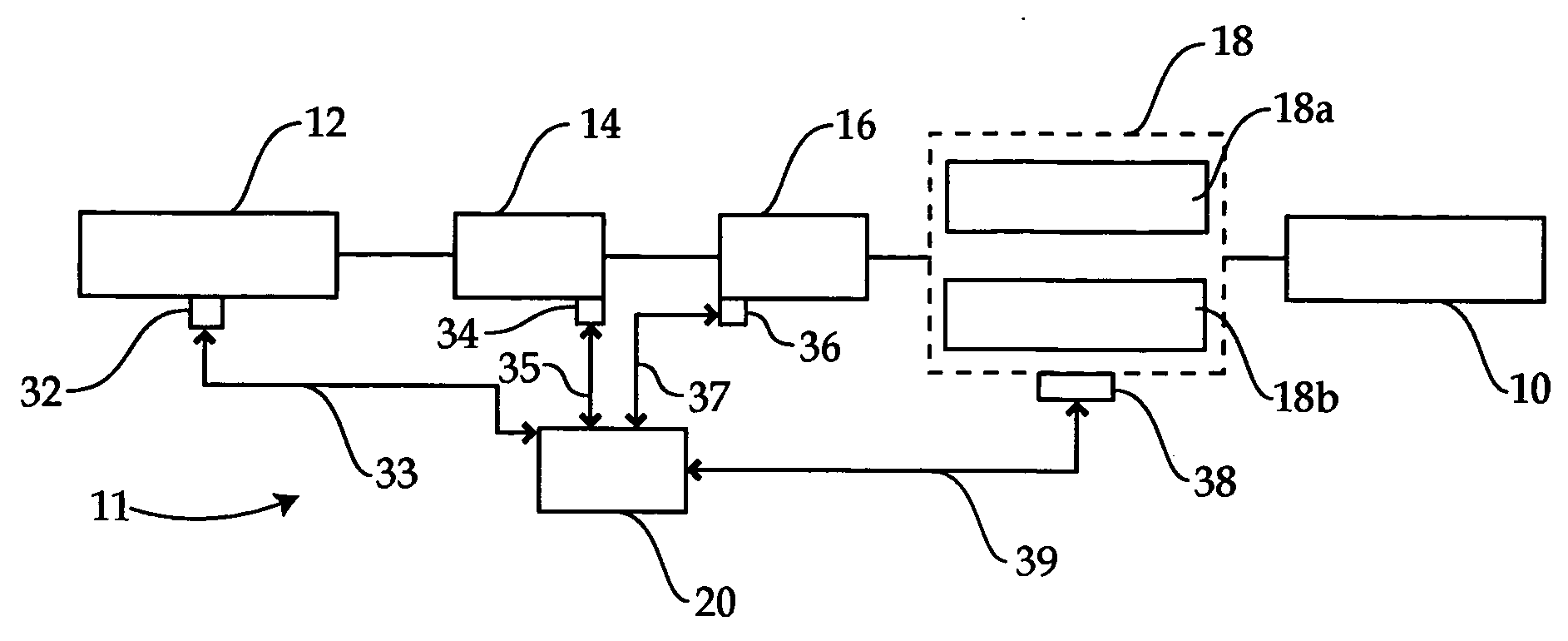
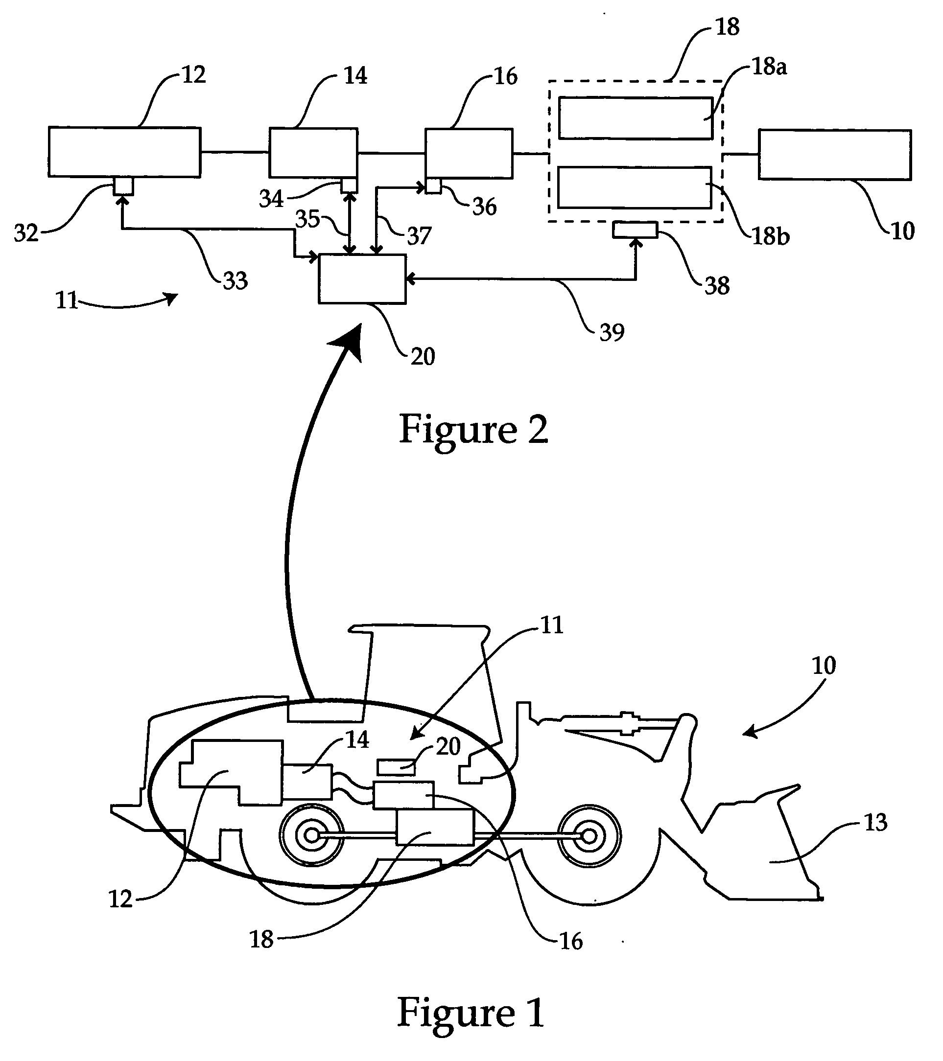
[0016] Referring to FIG. 1, there is shown a hydrostatic drive work machine 10. Work machine 10 includes a hydrostatic drive 11 disposed therein, including an engine 12, a variable displacement pump 14, a variable displacement motor 16 and a gearbox or transmission 18 having at least two gears 18a and 18b. An electronic control module 20 is further provided, and is operable to electronically control various of the components of hydrostatic drive 11 to slow the same, for example, where the work machine is slowed and shifted to neutral, as described herein. The present disclosure is concerned primarily with a process of slowing work machine 10, however, in many instances slowing of work machine 10 will be followed by shifting to neutral, e.g. disengaging both of gears 18a and 18b. This will typically be the case where, for example, work machine 10 is being parked or will remain stopped for some time. Work machine 10 is illustrated as a loader having a bucket 13, however, it should be ...


PUM


Abstract

A method of reducing speed in a hydrostatic drive work machine, and a hydrostatic drive work machine are provided. The method includes the steps of retarding the work machine by at least one of, upstroking a variable displacement hydraulic motor thereof, and downstroking a variable displacement pump coupled with the motor. An offgoing clutch pressure is dropped after each of the motor and pump displacements reaches a predetermined point. The steps of slowing the work machine are carried out by adjusting the respective displacements at rates based on a predetermined acceleration limit and/or a predetermined jerk limit of the work machine. The hydrostatic drive work machine further includes an electronic control module having a control algorithm recorded thereon for to neutral.

Description

TECHNICAL FIELD [0001] The present disclosure relates generally to hydrostatic drive work machines, and relates more particularly to a process and software control algorithm for slowing such a machine. BACKGROUND [0002] Hydrostatic or “hystat” drive refers generally to a drive train or portion of a drive train in a work machine utilizing hydraulic fluid pressurized by engine rotation as the motive force for propelling the work machine. In a typical design, a pump is driven with an output shaft of the engine and provides pressurized hydraulic fluid to a hydraulic motor, in turn coupled with one or more axles of the work machine. In most hystat drive work machines, the pump and motor each have a variable displacement, allowing the relative torque and speed of a drive shaft to be continuously varied. [0003] Where it is desirable to provide a relatively higher torque to the work machine wheels or tracks, the displacement of the motor will be relatively large such that at a given hydraul...

Claims


Application Information

Patent Timeline
IPC IPC(8): F01B13/04F16H61/40F16H61/4157F16H61/42F16H61/421F16H61/423F16H61/431F16H61/46F16H61/462
CPCF16H61/061F16H61/4157F16H61/421Y10T74/19163F16H61/431F16H61/46F16H61/462F16H61/423F16H47/02F16H61/42
Inventor SHAH, VAIBHAV H.
Owner CATERPILLAR INC
Why Eureka
Try Eureka