Oven
- Summary
- Abstract
- Description
- Claims
- Application Information
AI Technical Summary
Benefits of technology
Problems solved by technology
Method used
Image

Examples
first embodiment
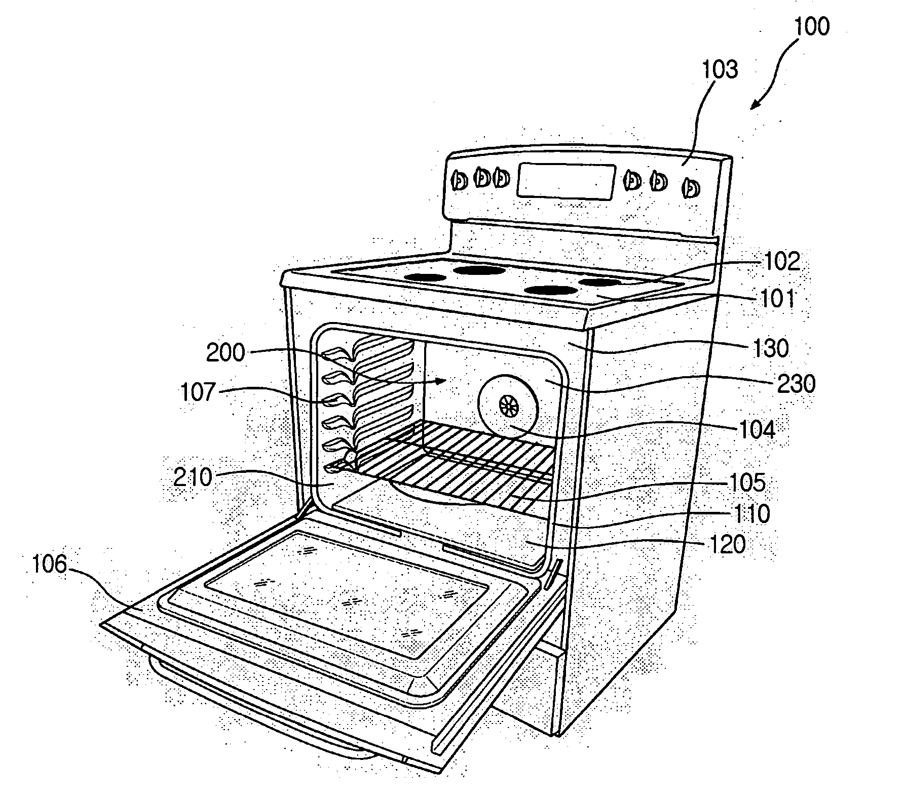
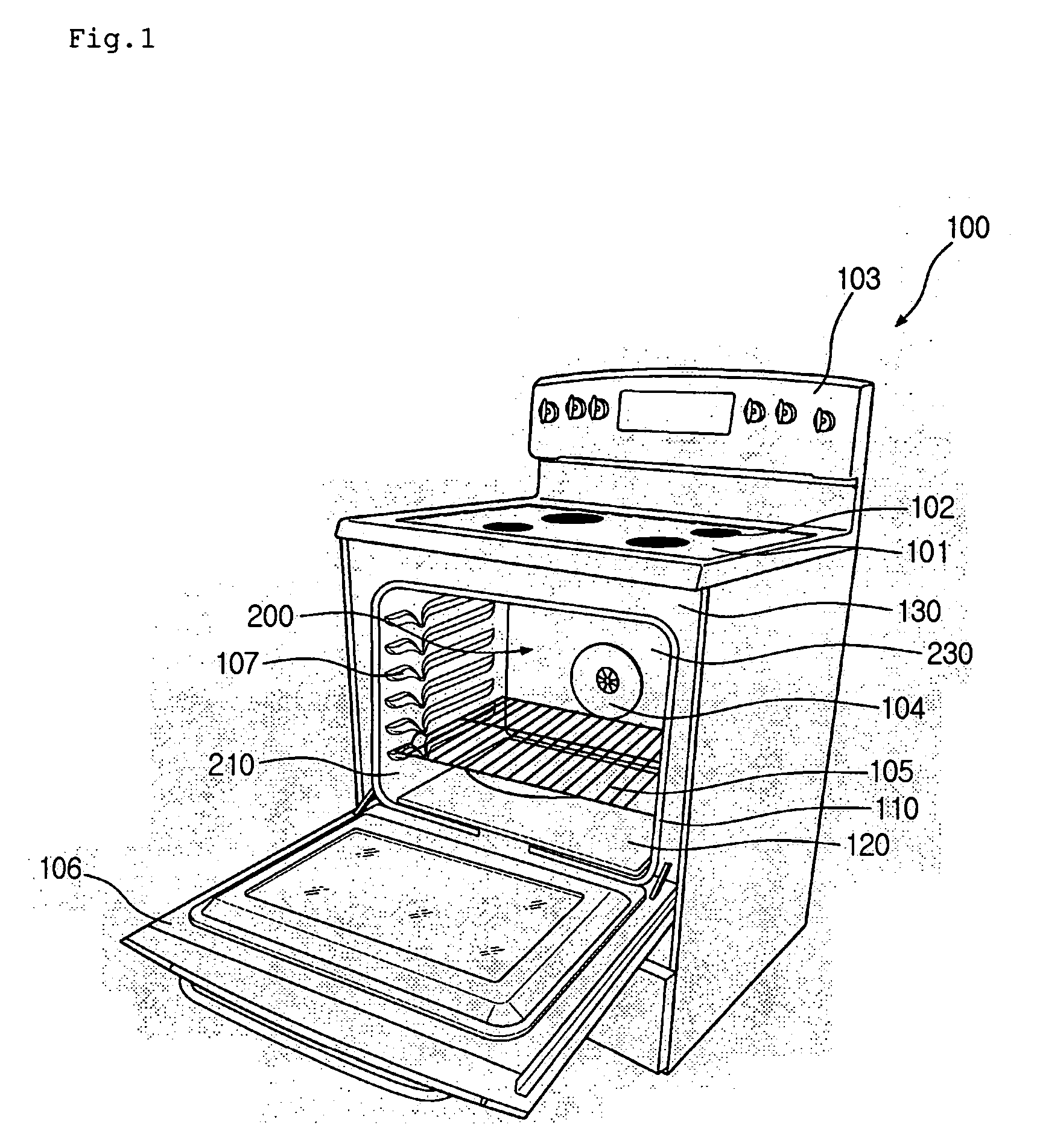
[0036]FIG. 1 is a perspective view of an oven according to the present invention.
[0037] Referring to FIG. 1, the oven 100 includes a door 106 mounted on a front side, for being opened / closed, and a cavity 200 opened / closed by the door 106. The cavity 200 is a space for cooking food. The oven 100 further includes a convection heater and a fan 104 disposed on the backside of the cavity 200 to act on the cavity 200.
[0038] The cavity 200 is formed by side plates 210, a rear plate 230, a lower plate 220 (of FIG. 2), and an upper plate 240 (of FIG. 2). These plates will be described later.
[0039] The side plates 210 and the lower plate 220 are coupled to a front plate 130, which constitutes a front side of the oven 100. The front plate 130 is shielded by the door 106 when the door 106 is closed.
[0040] A sealing member 110 is installed in the front plate 130 along the outer edge of the cavity 200. The sealing member 110 blocks a gap between the door 106 and the front plate 130 when the d...
second embodiment
[0053]FIG. 3 is a side view of a cavity assembly adopted to an oven according to the present invention.
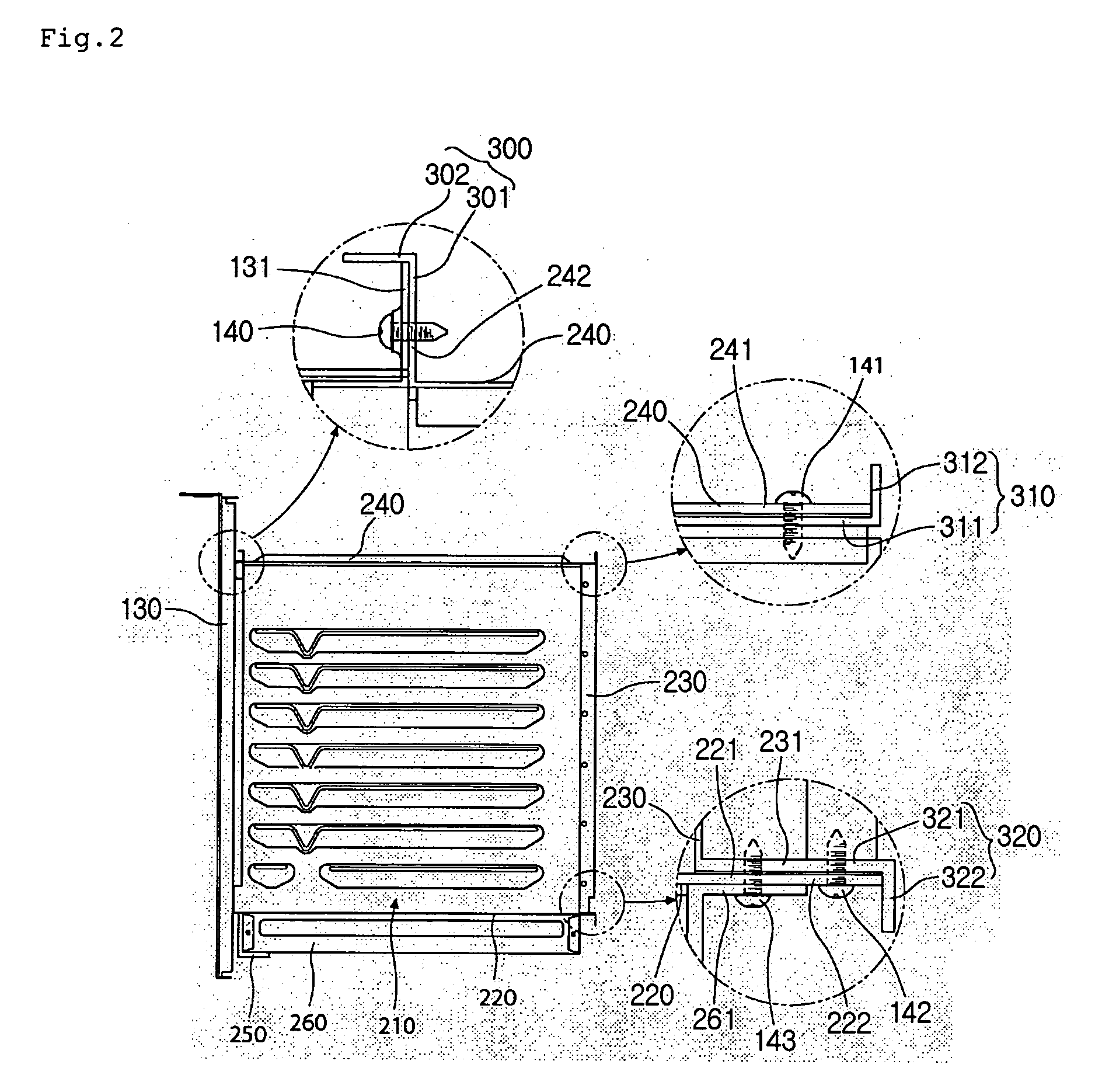
[0054] Referring to FIG. 3, a coupling portion 300 of the upper plate 240 includes a connection portion 301, a horizontal block 303 having a shape bent from the connection portion 301 to a front side, and a vertical block 304 having a shape bent from the horizontal block 303 to a lower side. Each of The horizontal block 303 and the vertical block 304 may be defined as blocks. The connection portion 301, the horizontal block 303, and the vertical block 304 encloses the coupling portion 131 of the front plate 130. Accordingly, a gap between the coupling portion 131 and the connection portion 301 of the front plate 130 may be doubly blocked by the horizontal block 303 and the vertical block 304. Therefore, it is possible to more reliably prevent heat in the inside of the cavity 200 from leaking out to the outside through the gap.
[0055] The coupling portions 310 and 320 of the rear pl...
third embodiment
[0056]FIG. 4 is a side view of a cavity assembly adopted to an oven according to the present invention.
[0057] Referring to FIG. 4, a horizontal block 303 has a shape bent from a connection portion 301 of the upper plate 240 to a front side and a vertical block 305 has a shape bent from the horizontal block 303 to a lower side. A fixing member 140 passes through the vertical block 305, the coupling portion 131 of the front plate 130, and the connection portion 301. Accordingly, a gap between the vertical block 305, the coupling portion 131, and the connection portion 301 may be minimized by coupling force of the fixing member 140. Therefore, it is possible to more reliably prevent heat in the inside of the cavity 200 from leaking out to the outside through the gap.
[0058] The coupling portions 310 and 320 of the rear plate 230 include vertical blocks 313 and 323 having shapes bent from the connection portions 311 and 321 to an upper side and a lower side, respectively, and horizontal...
PUM
 Abstract
Description
Claims
Application Information
 - R&D
- Intellectual Property
- Life Sciences
- Materials
- Tech Scout
- Unparalleled Data Quality
- Higher Quality Content
- 60% Fewer Hallucinations
Browse by: Latest US Patents, China's latest patents, Technical Efficacy Thesaurus, Application Domain, Technology Topic, Popular Technical Reports.
© 2025 PatSnap. All rights reserved.Legal|Privacy policy|Modern Slavery Act Transparency Statement|Sitemap|About US| Contact US: help@patsnap.com