Current limit circuit and power supply including same

Active Publication Date: 2006-07-13
ARTESYN TECH
View PDF14 Cites 17 Cited by
  • Summary
  • Abstract
  • Description
  • Claims
  • Application Information

AI Technical Summary

Benefits of technology

[0010] The power supply may further include a control circuit connected to the current limit circuit. The current limit circuit may generate the pulse width modulated (PWM) control signal to control the primary switch of the converter. Also, the current limit circuit may include an averaging circuit connected to the functional circuit. The averaging circuit may average the output signal (Iout) of the functional circuit to generate a signal ({overscore (Iout )}) indicative of the average output current of the converter. The control circuit may monitor the {overscore (Iout )} signal to detect for overcurrent conditions at the output of the converter, in which case the control circuit may reduce the duty cycle of the primary switch.

Problems solved by technology

Since the slope of the output current of the converter (e.g., the current through an inductor of the output filter circuit) is related to the operating point of the converter, attempting to control the output current of a power converter with only the D state information can result in considerable errors.
Unfortunately, to manage the power dissipation in the sensing element the developed voltage must be minimized.
In an optimized sensor circuit the developed voltage is well below the forward conduction drop of silicon diodes and in general makes direct signal processing difficult and replete with parasitic error terms.

Method used


Image

  • Current limit circuit and power supply including same
  • Current limit circuit and power supply including same
  • Current limit circuit and power supply including same

Examples


Embodiment Construction

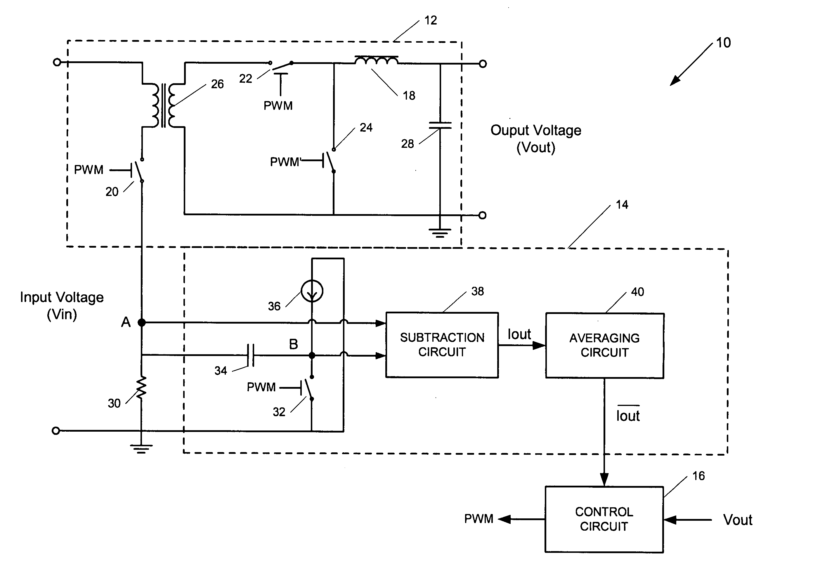
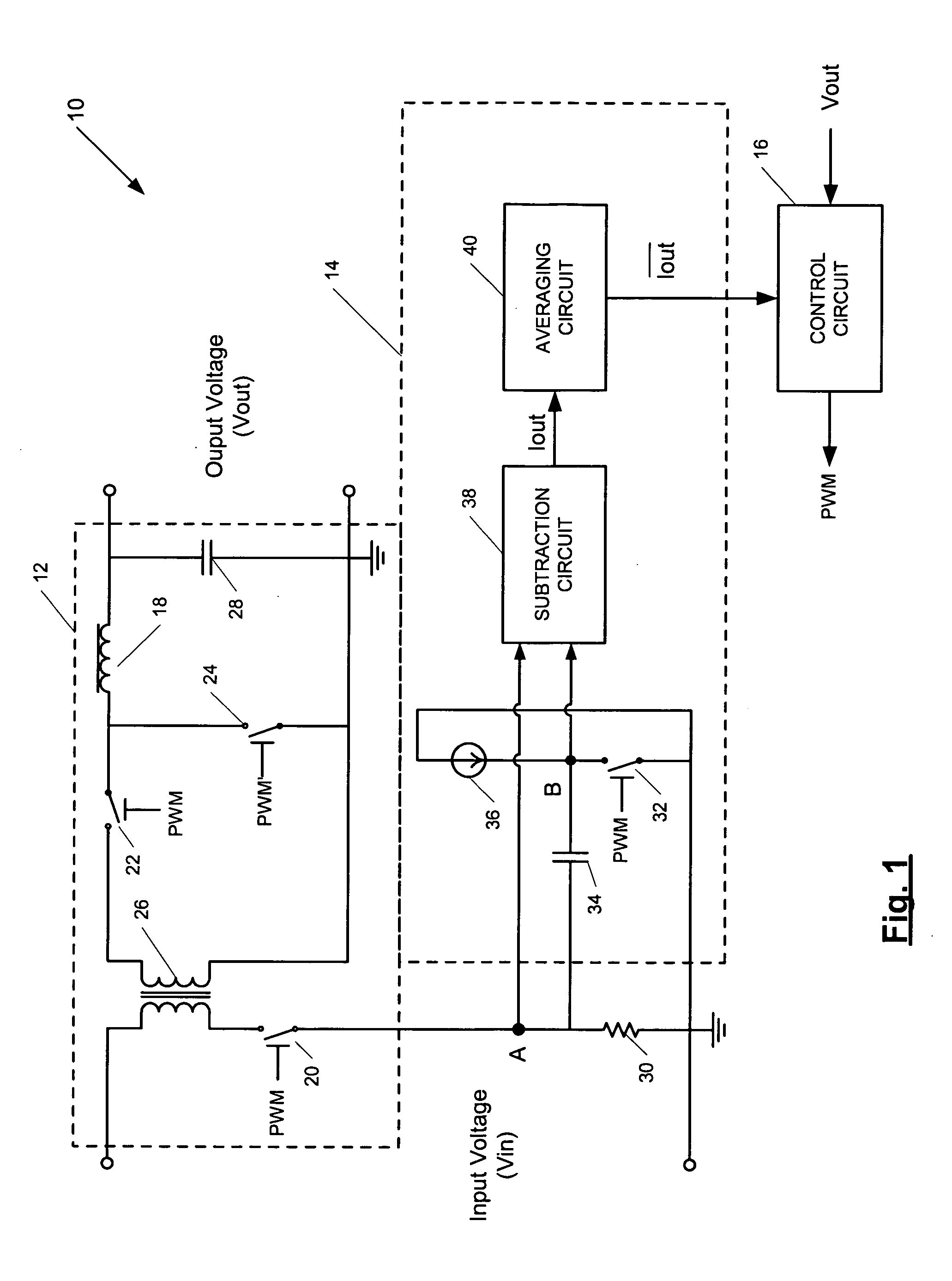
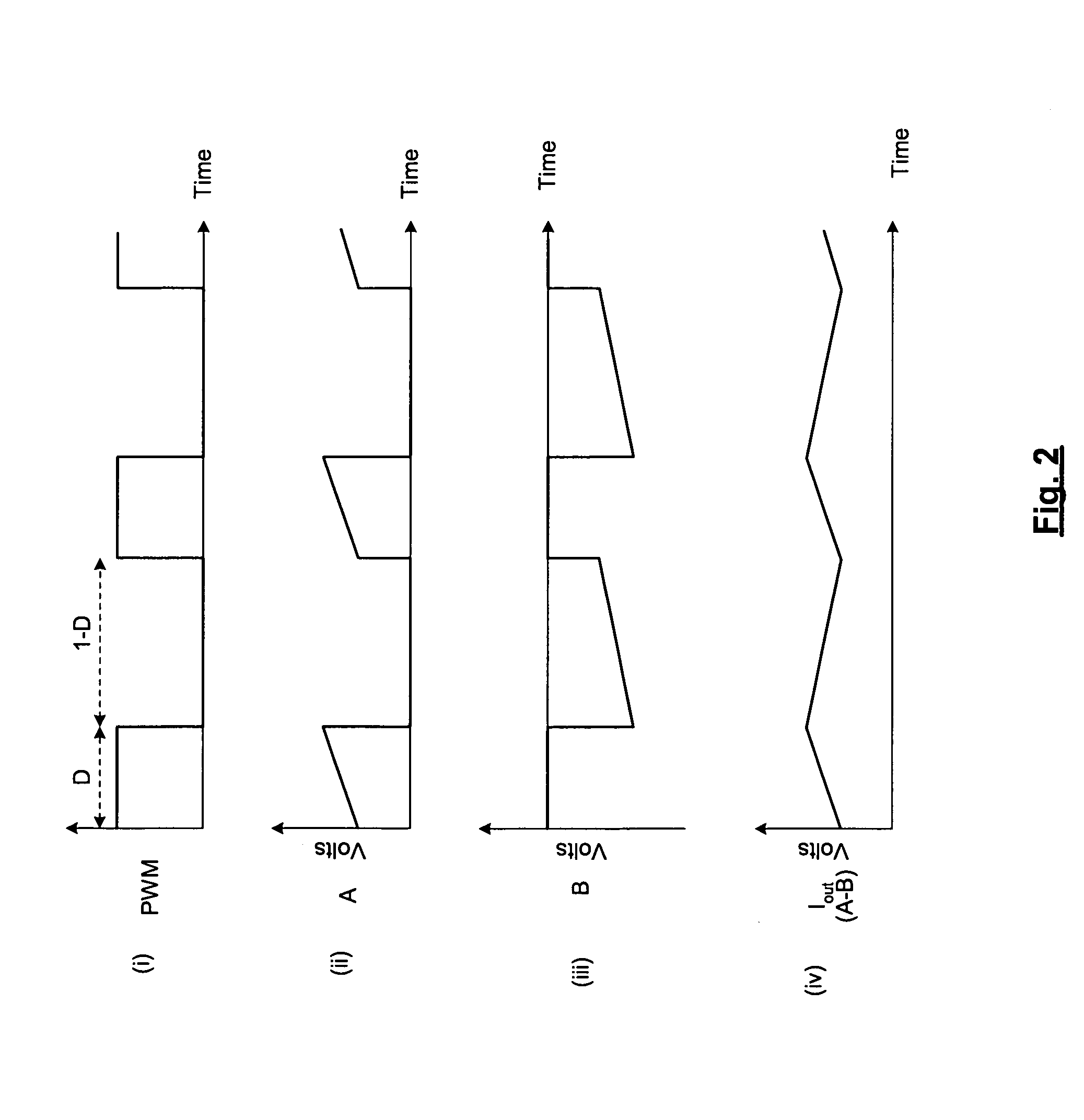
[0016]FIG. 1 is a diagram of a power supply 10 according to various embodiments of the present invention and FIGS. 2(i)-(iv) are idealized voltage waveforms illustrating the operation of the power supply 10. The power supply 10 includes a DC / DC converter 12 that converts an input voltage (Vin) to an output voltage (Vout) for powering a load (not shown). The power supply 10 also includes a current limit circuit 14 and a control circuit 16. The current limit circuit 14 is for developing, according to various embodiments, a signal ({overscore (Iout )}) whose voltage is proportional to the average output current of the converter 12 (e.g., the current through output inductor 18). The control circuit 16 may generate a pulse width modulated control signal (PWM) based on either the output voltage or the output current of the converter 12 to control the various switches of the power supply 10, including the primary input switch 20. That is, the control circuit 16 may modulate the duty cycle ...


PUM


Abstract

The present invention is directed generally to a power supply. According to various embodiments, the power supply includes at least one DC / DC converter. The converter includes a primary switch controlled by a pulse width modulated control signal such that the primary switch is on for a D time period of each switching cycle of the converter and is off for a 1-D time period of each switching cycle. Also, the power supply includes a current sensing element connected in series with the primary switch. In addition, the power supply includes a current limit circuit connected to the current sensing element. The current limit circuit includes a functional circuit having a first input responsive to a first signal whose voltage is proportional to the output current of the converter during the D time period of the switching cycle of the converter. A second input of the functional circuit is responsive to a second signal whose voltage is proportional to the output current of the converter during the 1-D time period of the switching cycle of the converter. In that way, the voltage of the output signal of the functional circuit is proportional to the output inductor current of the converter over both the energy storage phase (the D interval) and the energy deliver phase (the 1-D) interval of the converter.

Description

BACKGROUND [0001] 1. Field of the Invention [0002] The present invention relates generally to DC-DC power conversion. [0003] 2. Background of the Invention [0004] DC-to-DC power converters are power-processing circuits that convert an unregulated input DC voltage to a regulated DC output voltage. Switched-mode DC-to-DC power converters typically include an inverter, a transformer having a primary winding coupled to the inverter, a rectifying circuit coupled to a secondary winding of the transformer, and a filter connected between the rectifying circuit and the load. The inverter typically includes a pulse width modulated (PWM) switching device (i.e., the primary switch), such as a MOSFET, that converts the DC input voltage to an alternating voltage, which is magnetically coupled from the primary winding of the transformer to the secondary winding. A PWM control circuit regulates conduction of the PWM switching device. The rectifying circuit rectifies the alternating voltage on the s...

Claims


Application Information

Patent Timeline
IPC IPC(8): G05F1/40G05F1/44
CPCH02M1/32H02M3/33507
Inventor PERRY, MARTYPOYNTON, IAN
Owner ARTESYN TECH
Why Eureka
Try Eureka