[0009] In certain embodiments, the portion of the implant that secures the
cortical bone, e.g., the generally flat surface, is formed of a compliant material, e.g., elastic
titanium or elastic stainless steel that will conform to an irregular surface of the bone. The generally flat surface will have an elastic property that will allow the structure to conform to the bone and form a tight seal against the bone. By forming a tight seal the compliant structure (1) helps reduce the chances of bacterial infiltration between the implant and the bone, and (2) reduces the amount of movement between the bone and implant.
[0010] A compliant structure will also allow for small adjustments to be made by rotating the implant. This may be advantageous where, for example, the trajectory of drilling the receiving hole in the bone is not correct to achieve alignment with adjacent teeth. The hole in the implant that receives the abutment may be offset relative to the axis of the implant. Thus, as the implant is rotated, the angle of the abutment relative to the adjacent teeth will adjust. By use of a compliant material for the generally flat surface, the curved region, or “wings,” can be lifted, the implant rotated to achieve the correct angle for the abutment, and the curved region allowed to fall back in place around the
bone structure. Here, after rotation, the wings may have to fold along a new line to tightly
wrap around the
bone structure. Use of a compliant material allows the wings to fold along a new line after the implant is rotated.
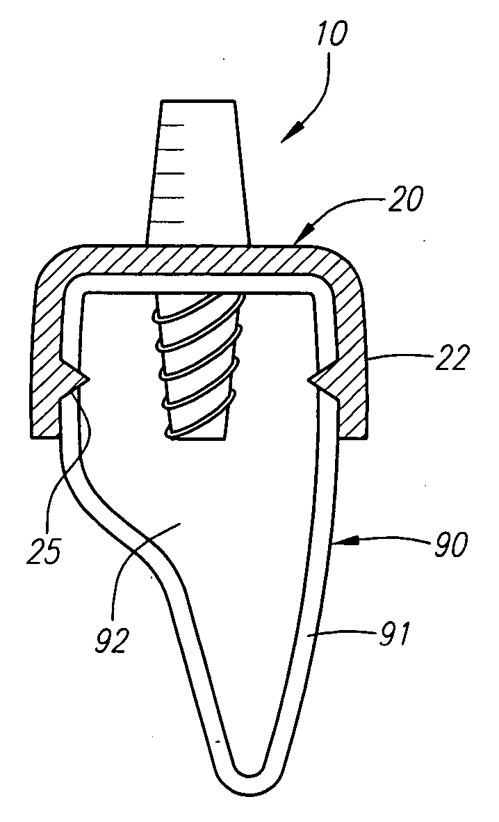
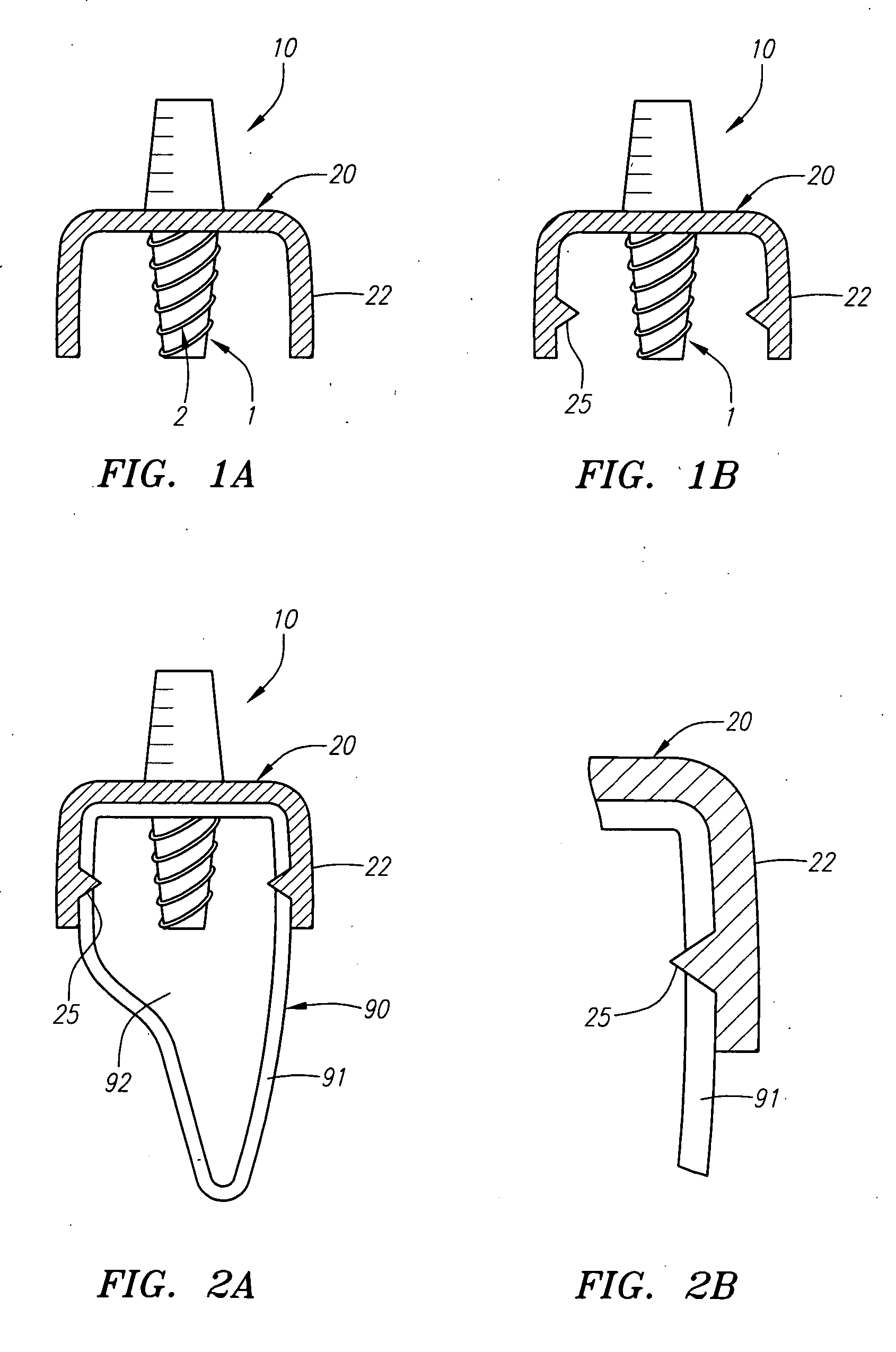
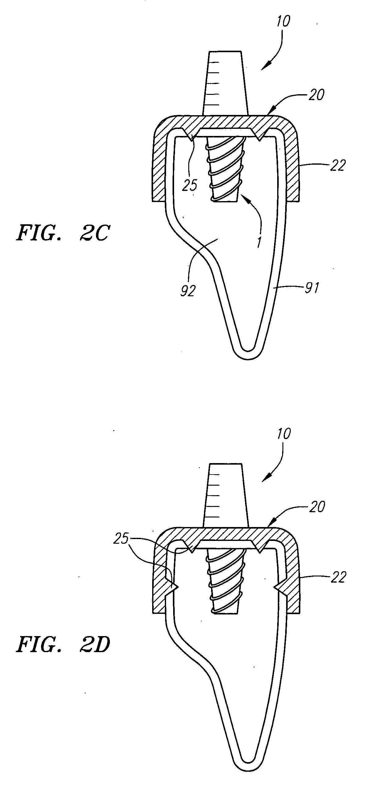
[0011] Bacterial infiltration can cause bone reduction and degradation. A tight fit is therefore desired between the bone and the flat structure. The curved regions at the ends of the generally flat structure may be biased inwardly to assure the formation of a tight seal with the
bone structure. In this manner the curved regions will be pried open, placed over the
ridge of the maxilla or mandible, and released to snap down tightly over the maxilla or mandible. In some cases the
titanium or stainless steal is
cut with thin spots to give
strain relief and bending properties. In other cases, the bone structure is ground down to make a flat surface to receive the implant.
[0017] In use, the dental prosthetic can function as a replacement for
tooth loss.
Osteotomy is created by drilling into the maxilla or mandible at the location of the
missing tooth. The elongate threaded implant is inserted into position within the trabecular region of the
jaw bone. An adaptor is secured to the elongate threaded implant. An abutment and compliant brace are then secured to the adaptor, wherein a portion of the abutment extends beyond the maxilla or mandible. The compliant brace is located between the first region of the abutment that is adapted to receive the crown and the adaptor. The abutment and compliant brace can be secured to the adaptor by securing a region of the abutment through an opening of the compliant brace into a region of the abutment. This could be accomplished by screwing a threaded region of the abutment through an opening of the compliant brace into a threaded region of the elongate threaded implant. The first, second, and third elongate extensions of the compliant brace are then adjusted to engage the surface of the cortical region of the maxilla or mandible. These extensions can be adjusted by bending or shaping the extensions to conform to the surface of the
cortical bone or the extensions may be supplied in a pre-formed shape. The pre-formed or pre-bent extensions could then be re-shaped or “pried” open to fit over the boney
ridge. The compliant brace can optionally be further stabilized by anchoring the extensions to the maxilla or mandible. The anchoring element(s) may comprise a barb, bone tack, or other suitable structure. A crown is then secured to the abutment.
[0018] The compliant brace of these prosthetics is typically made from a flexible material such as titanium, stainless steel, or other flexible material suitable for use as a
dental implant and known in the art. The compliant brace will have an elastic property that will allow the structure to conform to the bone and form a tight seal against the surface of the bone. By forming a tight seal, the compliant brace helps reduce the chances of bacterial infiltration between the implant and the bone, and reduces the movement between the bone and implant by acting as an additional load-bearing structure. The compliant brace will also allow for small adjustments to be made by rotating the implant and / or changing the angle of the abutment. The thin, elongate extensions will allow the tissue (gingivae) surrounding the
missing tooth to grow around between the extensions, thereby reattaching themselves to the
jaw bone. This further assists the stabilization of the implant.
[0019] The compliant brace may have a generally planar region, wherein the second and third elongate extensions extend from the generally planar region in a direction substantially opposite from the first elongate extension. This planar region may have smooth, rounded edges to enhance
soft tissue encapsulation. The generally planar region of the compliant brace may also have an outer region that is generally circular in shape. The compliant brace may also have a generally circular opening in the generally planar region. Optionally, the opening in the generally planar region may be any shape that can be disposed about the second region of the abutment. At least one of the first, second, or third elongate extensions may also have a further anchoring element(s) adapted to secure the first, second, or third elongate extensions to the cortical region of the maxilla or mandible. Additionally, at least one of the first, second, or third elongate extensions may have a hole located along the extension or at the end of the extension in which a bone tack can be inserted to further anchor or stabilize the extension(s) to the
cortical bone. Furthermore, at least one of the first, second, or third elongate extensions may have generally rounded edges to enhance
soft tissue encapsulation.

