Selective adherence of stent-graft coverings

a stent and graft technology, applied in the field of implantable vascular grafts, can solve the problems of lack of other desirable features, lack of additional means, and some subsequent retraction, and achieve the effect of preventing restenosis or local thrombosis

Inactive Publication Date: 2006-07-13
BARD PERIPHERAL VASCULAR
View PDF26 Cites 52 Cited by
  • Summary
  • Abstract
  • Description
  • Claims
  • Application Information

AI Technical Summary

Benefits of technology

[0037] In accordance with the present invention, selective bonding of expanded PTFE luminal and abluminal layers encapsulates the endoluminal stent and isolates the stent from both the tissue forming the anatomical passageway as well as any fluid, such as blood, bile, urine, etc. which may pass through the anatomical passageway. The presence of slip planes or pockets formed by the selectively adhered regions of ePTFE: i) permits freedom of movement of stent elements within the encapsulating covering during both expansion and contraction of the stent along either its radial or longitudinal axes; ii) permits uniform folding of the ePTFE stent covering material which is complementary to the structure of the stent element lattice; iii) permits movement of the stent relative to the ePTFE encapsulating layers; iv) reduces forces required to compress or dilate the stent in the case of elastically or thermally self-expanding stents; v) reduces radial expansion pressures required to balloon expand an ePTFE encapsulated stent; and vi) provides void regions which may be used in conjunction with the microporous microstructure of the ePTFE covering material to retain and release bioactive substances, such as anticoagulant drugs, anti-inflammatory drugs, or the like.
[0039] The present invention also encompasses selective bonding of multiple polymeric layers to create an inflatable structure. Such a structure can be inflated by fluids delivered through lumens within the delivery catheter. The selective bonding method allows creation of devices with multiple adjacent channels or pockets. Some of these pockets can be pre-filled with a therapeutic drug to prevent restenosis or local thrombosis. Alternate pockets can be arranged for fluid inflation after the device is inserted.

Problems solved by technology

However, if such grafts are radially expanded within a blood vessel, they will exhibit some subsequent retraction.
Further, such grafts usually require additional means for anchoring the graft within the blood vessel, such as sutures, clamps, or similarly functioning elements.
Although stents and stent / graft combinations have been used to provide endovascular prostheses that are capable of maintaining their fit against blood vessel walls, other desirable features are lacking.
Perhaps the most serious problem is that the folding during compression actually encompasses folding of the stent itself, which unduly stresses the stent material and may result in structural failure.
These stents have superior hoop strength against compressive forces but should this strength be overcome, the devices will deform and not recover.
This has posed difficulty particularly with the self-expanding stents.
Because the struts of the stent are completely encapsulated, resistance of the polymer may cause folding or stressing of the struts during compression.

Method used


Image

  • Selective adherence of stent-graft coverings
  • Selective adherence of stent-graft coverings
  • Selective adherence of stent-graft coverings

Examples


Embodiment Construction

in conjunction with the accompanying drawings that are first briefly described.

BRIEF DESCRIPTION OF THE DRAWINGS

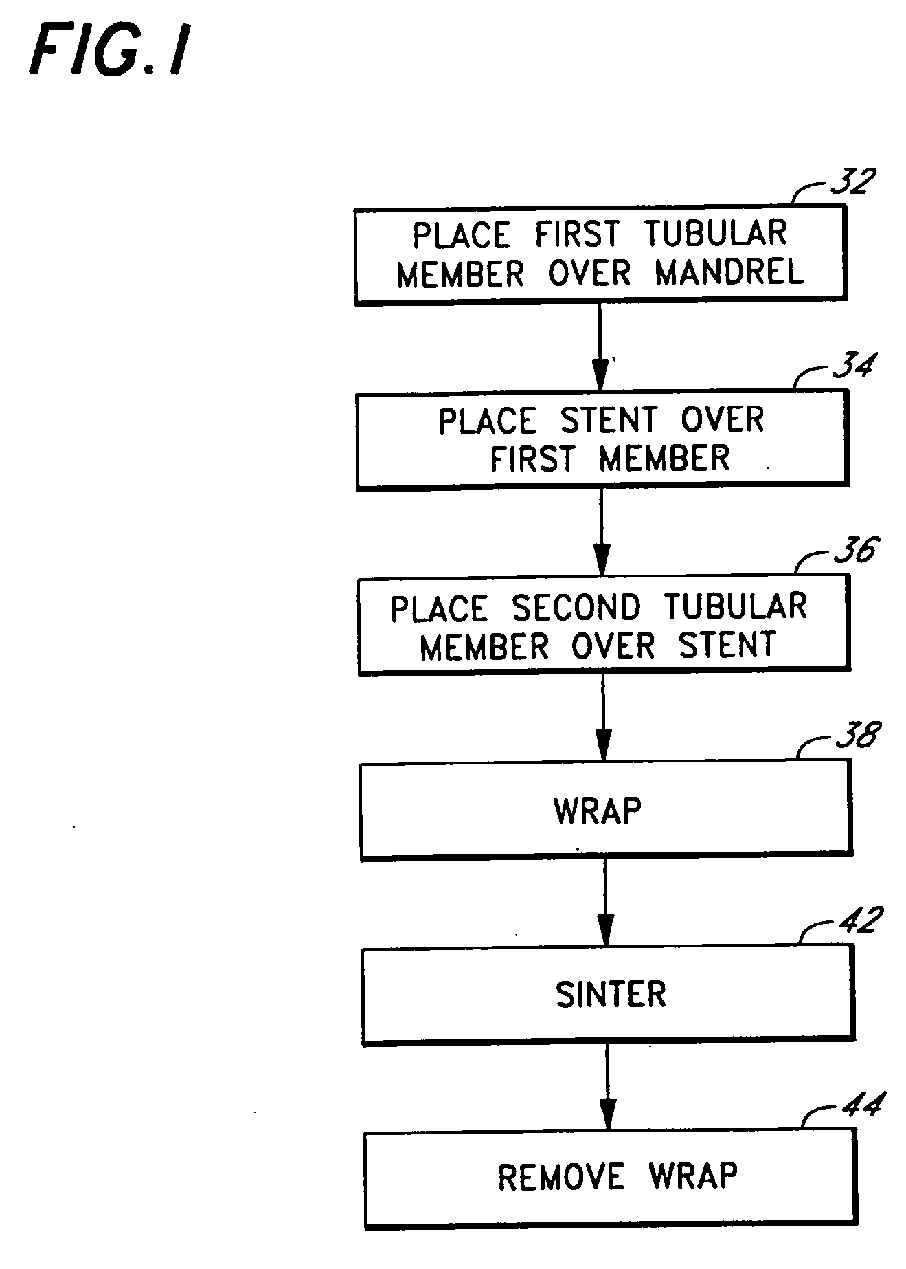
[0044]FIG. 1 is a is a process flow diagram illustrating a preferred method of making a stent-graft device

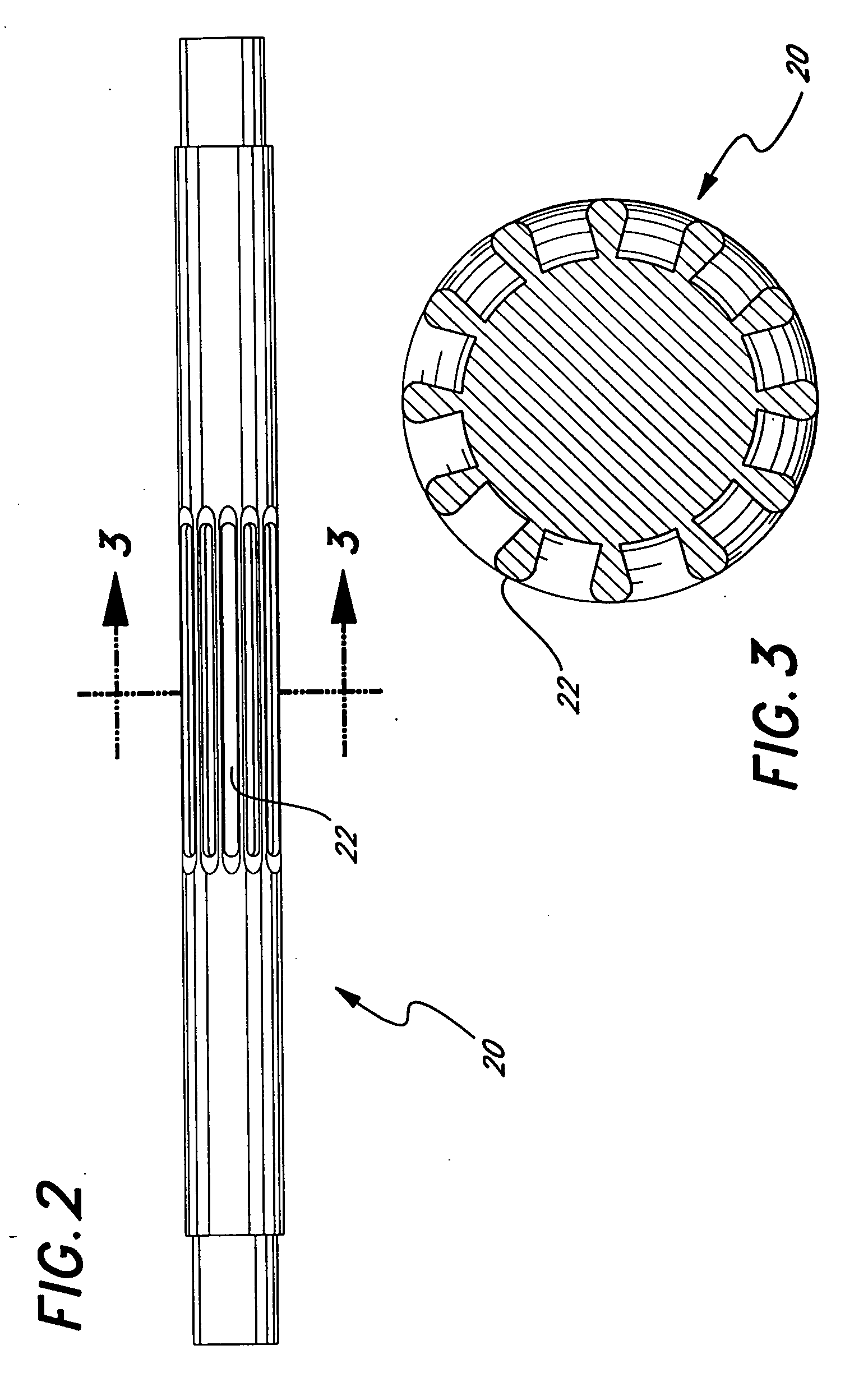
[0045]FIG. 2 is a is a perspective view of a mandrel having longitudinal ridges or splines.

[0046]FIG. 3 is a is a cross-section view of the mandrel shown in FIG. 2.

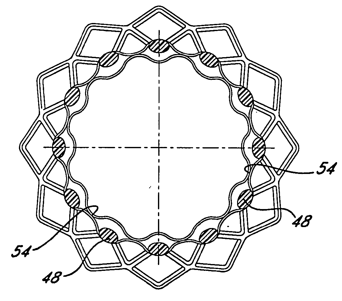
[0047]FIG. 4 is a perspective view of a stent-graft device illustrating selected regions of bonding between the luminal and abluminal stent covers and a plurality of slip plane pockets intermediate the luminal and abluminal stent covers.

[0048]FIG. 5 is a is a cross-sectional view taken along line 5-5 of FIG. 4.

[0049]FIG. 6 is a scanning electron micrograph illustrating a selectively bonded region and a slip plane pocket with a stent element residing therein.

[0050]FIG. 7 is a is a perspective view of a mandrel having circumferential ridges (as opposed to longitudinal splines).

[0051]FIG. 8 is a is a fl...


PUM

PropertyMeasurementUnit
temperatureaaaaaaaaaa
diameteraaaaaaaaaa
lengthaaaaaaaaaa

Abstract

An endoluminal prosthesis including a first polymer member bonded to a second polymer member to selectively encapsulate a stent. Selective bonding between the first and second polymer members results in unbonded regions or pockets that accommodate movement of the stent, permitting compression of the prosthesis using minimal force and enabling collapse of the prosthesis to a low profile. The pockets are believed to encourage enhanced cellular penetration for rapid healing and may contain bioactive substances.

Description

PRIORITY [0001] This application is a continuation of U.S. application Ser. No. 10,410,589, filed Apr. 9, 2003, now U.S. Pat. No. 7,004,966, which is a continuation of U.S. application Ser. No. 09 / 764,811, filed Jan. 16, 2001, now U.S. Pat. No. 6,547,814, which is a division of U.S. application Ser. No. 09 / 409,209, filed Sep. 30, 1999, now U.S. Pat. No. 6,245,099, which claims the benefit under 35 U.S.C. § 119(e) to U.S. Provisional Application No. 60 / 102,518, filed Sep. 30, 1998, each of which is incorporated by reference into this application as if fully set forth herein.BACKGROUND OF THE INVENTION [0002] The use of implantable vascular grafts comprised of PTFE is well known in the art. These grafts are typically used to replace or repair damaged or occluded blood vessels within the body. However, if such grafts are radially expanded within a blood vessel, they will exhibit some subsequent retraction. Further, such grafts usually require additional means for anchoring the graft wi...

Claims


Application Information

Patent Timeline
Patent Type & Authority Applications(United States)
IPC IPC(8): A61F2/06A61F2/00
CPCA61F2/07A61F2/91A61F2002/072A61F2250/0003A61F2250/0014A61F2230/0054A61F2250/0067A61F2/90A61F2002/075A61F2230/005A61F2250/0039A61F2240/001B29C65/02B29C65/48B29L2031/753
Inventor EDWIN, TARUN J.RANDALL, SCOTT L.MCCREA, BRENDAN J.BANAS, CHRISTOPHER E.
Owner BARD PERIPHERAL VASCULAR
Why Eureka
Try Eureka