
Comparing a configuration diagram to an actual system

a configuration diagram and actual system technology, applied in the field of system configuration, can solve the problems of difficulty for users to create various computer programs, and achieve the effect of facilitating user payment and billing

Active Publication Date: 2006-07-13
NATIONAL INSTRUMENTS
View PDF29 Cites 67 Cited by
  • Summary
  • Abstract
  • Description
  • Claims
  • Application Information

AI Technical Summary

Benefits of technology

[0026] In some embodiments, a merged configuration diagram may be generated representing a “merged” system comprising at least a subset of a union (in the set-theoretic sense) of the respective components of the first system and the actual system. In some embodiments, the merged configuration diagram may be generated as the configuration diagram and the actual system (or representation thereof) are traversed or walked, thus obviating any intermediate data structures, e.g., intermediate lists. For example, the configuration diagram and the actual system (or representation thereof, e.g., another configuration diagram) may be traversed at least partially to determine a common component or resource, and then both (diagram / system) may be traversed starting with the common component in each. The method may then walk the respective configuration diagrams (and / or representations, e.g., graphs, data structures, etc.), adding and connecting components in a new configuration diagram (the merged configuration diagram) corresponding to those encountered in the traversals of the first system and the actual system. Note that where matching components are encountered in the first system and the actual system, only one corresponding component may be added to the merged configuration diagram, thereby avoiding redundancies in the merged configuration diagram. Alternatively, the merged configuration diagram may be generated by adding to the configuration diagram of the first system.
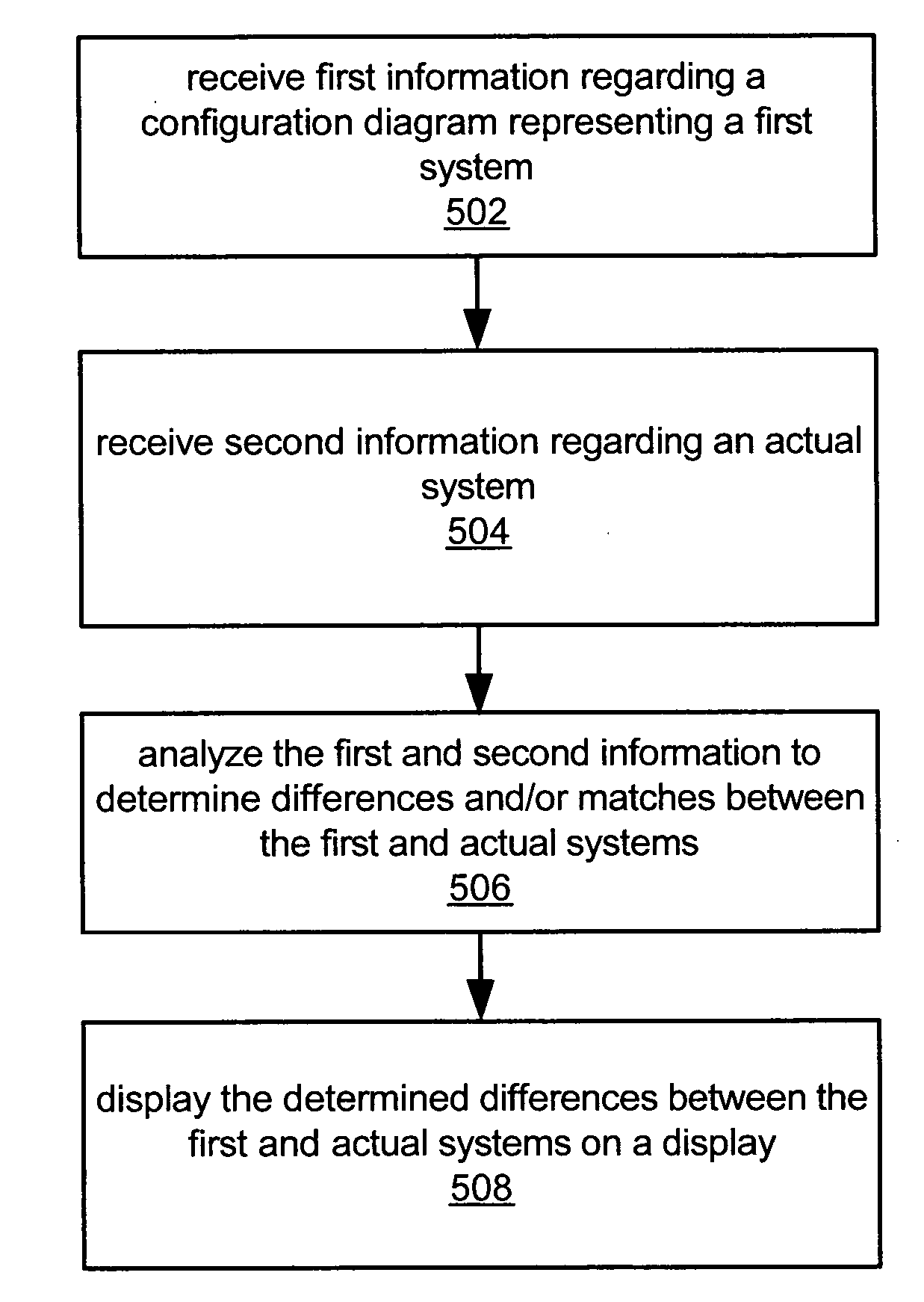
[0031] For example, in one embodiment, software executing on a client computer system, e.g. the users computer system, and / or software executing on a server computer, e.g. coupled to the client computer, may analyze the determined differences and may automatically initiate acquisition and / or purchase of the missing (one or more) components. In one embodiment, the software may automatically order the components without user input, e.g., via the network (e.g., the Internet), for example, if the user's billing or payment information (e.g., credit card number, credit account number, etc.) is already stored or available to the software. In other words, the system may comprise an e-commerce system that automatically (or at user initiation) orders and purchases the needed components based on the determined differences. In other embodiments, the user may be presented with a GUI, e.g., displayed on the client system and provided by the server and / or the client system, prompting the user for input regarding completion of the actual system. For example, the GUI may display the first configuration diagram, e.g., highlighting those components that are missing in the actual system, and may prompt the user with a “Complete the system?” message or equivalent. In response to a positive answer from the user, a search for and / or order of the missing components may then be performed. For example, one or more quotes for each missing component may be presented to the user, including, for example, cost, vendor, delivery times, and / or any other information useful for making a purchase decision, where the quotes may be retrieved from a database, via a network search engine, or any other source of quote information. As another example, the user may click on each of the missing components in the diagram, thereby invoking respective options related to that component, such as, for example, searching for similar components, ordering the component, etc. The GUI may also facilitate user entry or specification of payment information for acquiring the components where necessary. Note that in some cases, one or more of the needed components may be free, e.g., software components available for download from a server, etc.
[0034] Thus, the GUI may present user-selectable options for acquiring the components. As one example, the GUI may simply provide a list of the needed components (possibly numerous versions of each) and contact information for sources or vendors of the components, e.g., names, addresses, telephone numbers, websites or URLs, and so forth. As another example, the GUI may present various ordering options and / or means for acquiring the components, including, for example, user-selectable links for placing orders over a network, e.g., the Internet, or for downloading software and / or data. In some embodiments, the GUI may present information to help the user select components, such as, for example, cost, vendor, manufacturer, technical specifications, order fulfillment times, and so forth. The GUI may also facilitate user entry of payment, billing, or account information needed to purchase the components, as mentioned above.

Problems solved by technology

As a result, in many cases it is extremely difficult for a user to be able to create various computer programs and distribute these programs among devices in a distributed system.

Method used


Image

  • Comparing a configuration diagram to an actual system
  • Comparing a configuration diagram to an actual system
  • Comparing a configuration diagram to an actual system

Examples


Embodiment Construction

INCORPORATION BY REFERENCE

[0050] The following references are hereby incorporated by reference in their entirety as though fully and completely set forth herein:

[0051] U.S. patent application Ser. No. 08 / 870,262 titled “Method for Detecting Differences Between Graphical Programs,” filed on Jun. 6, 1999.

[0052] U.S. patent application Ser. No. 09 / 339,340 titled “System, Method and Memory Medium for Detecting Differences Between Graphical Programs,” filed on Oct. 24, 2000.

[0053] U.S. patent application Ser. No. 10 / 113,987 titled “A Configuration Diagram Which Displays a Configuration of a System,” filed on Apr. 1, 2002.

[0054] U.S. patent application Ser. No. 10 / 338,512 titled “Network-Based System for Analyzing a Client System and Generating a Configuration Diagram which Describes the Client System,” filed on Jan. 8, 2003.

[0055] U.S. Pat. No. 4,914,568 titled “Graphical System for Modeling a Process and Associated Method,” issued on Apr. 3, 1990.

[0056] U.S. Pat. No. 5,481,741 tit...


PUM


Abstract

System and method for determining differences and / or matches between a configuration diagram and an actual system. First information is received regarding a configuration diagram comprising a first plurality of nodes and graphically representing a first system, and second information is received regarding an actual system comprising a plurality components. At least a portion of the nodes may correspond to hardware devices, programs, and / or configuration data of the first system, and may be interconnected. The first and second information is analyzed to determine differences and / or matches between the configuration diagram and the actual system, e.g., between hardware, software, configuration, and / or connectivity, e.g., by traversing the configuration diagram or a data structure representing the diagram, and / or traversing the actual system or a data structure representing the actual system. An indication of the differences and / or matches is displayed on a display device, e.g., textually, or graphically, e.g., via a merged configuration diagram.

Description

PRIORITY DATA [0001] This application claims benefit of priority to U.S. Provisional Application Ser. No. 60 / 643,658, titled “Comparing a Configuration Diagram to an Actual System”, filed on Jan. 13, 2005, whose inventors were David W Fuller III and Mohammed Kamran Shah.FIELD OF THE INVENTION [0002] The present invention relates to the field of system configuration, and more particularly to a system and method for comparing a configuration diagram representing a system to an actual physical system. The invention further relates to methods for aiding the user to obtain and / or modify hardware and / or software components for the actual system so that the actual system can conform to the configuration diagram DESCRIPTION OF THE RELATED ART [0003] With the advent of networked computer systems, there has been a trend in computer software to provide more distributed software applications. For example, in some fields developers are attempting to distribute software applications among two or ...

Claims


Application Information

Patent Timeline
Patent Type & Authority Applications(United States)
IPC IPC(8): G06F9/45
CPCG06F8/34
Inventor FULLER, DAVID W. IIISHAH, MOHAMMED KAMRAN
Owner NATIONAL INSTRUMENTS
Learn More