Automated tightening shoe

a shoe and automatic technology, applied in the field of shoes, can solve the problems of lack of success and satisfaction, lack of provision for quick loosening of shoes, and no automated tightening system heretofore devised,

Inactive Publication Date: 2006-07-20
HANDS FREE ENTERPRISES LLC
View PDF4 Cites 39 Cited by
  • Summary
  • Abstract
  • Description
  • Claims
  • Application Information

AI Technical Summary

Benefits of technology

[0007] Accordingly, the primary objective of the present invention is to produce an automated tightening shoe, especially a sport or athletic shoe, that tightens snugly about the wearer's foot from both sides and that can be loosened easily. It is a further objective of the present invention to attain the primary objective by providing an automated tightening system which requires no complex or expensive parts, and which includes no parts that need frequent maintenance or periodic replacement. Another objective of the present invention is to provide an automated tightening shoe which is easy to operate and trouble-free in use.
[0025] Alternatively, another significant aspect and feature of the present invention is the use of drums having concave profile winding surfaces and the use of a ratcheted actuator spool being in close tolerance fit with upper and lower housings to prevent shoe lace jamming.

Problems solved by technology

However, none of the automated tightening systems heretofore devised has been entirely successful or satisfactory.
Major shortcomings of the automated tightening systems of the prior art are that they fail to tighten the shoe from both sides so that it conforms snugly to the wearer's foot, and that they lack any provision for quickly loosening the shoe when it is desired to remove the shoe from the wearer's foot.
Aspects of prior art automated tightening systems contributing to their lack of success and satisfaction have been (1) complexity, in that they involve numerous parts; (2) the inclusion of expensive parts, such as small electric motors; (3) the use of parts needing periodic replacement, e.g., a battery; and (4) the presence of parts requiring frequent maintenance.

Method used


Image

  • Automated tightening shoe
  • Automated tightening shoe
  • Automated tightening shoe

Examples


Embodiment Construction

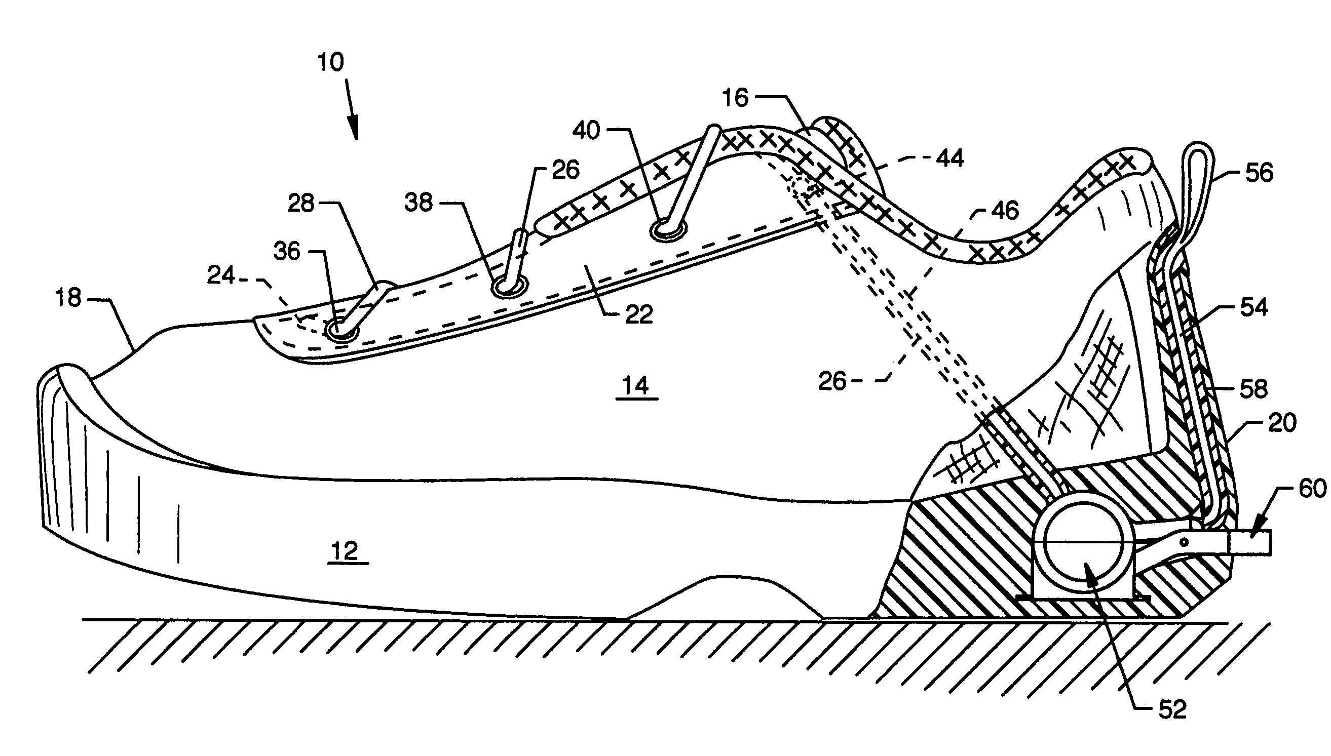
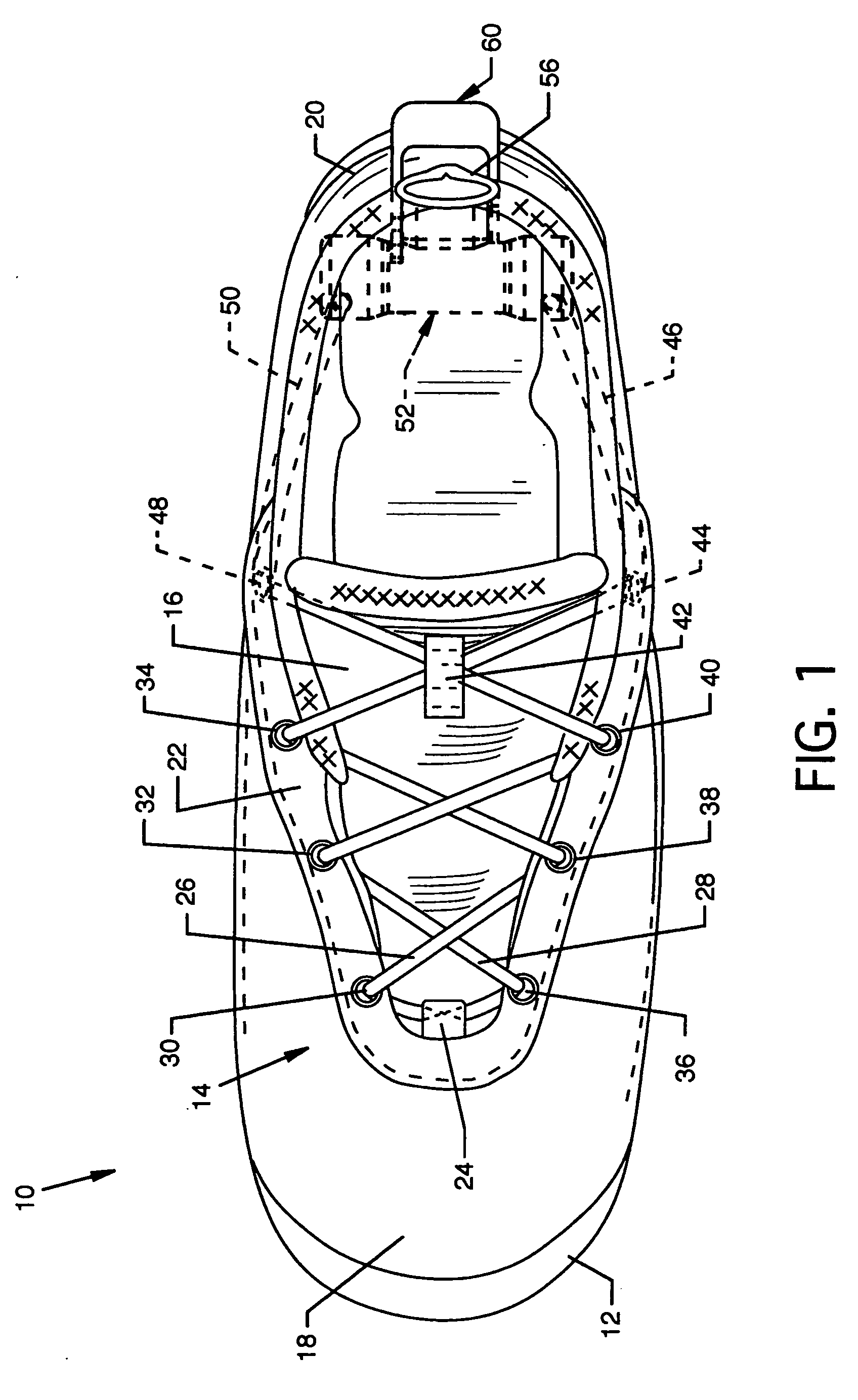
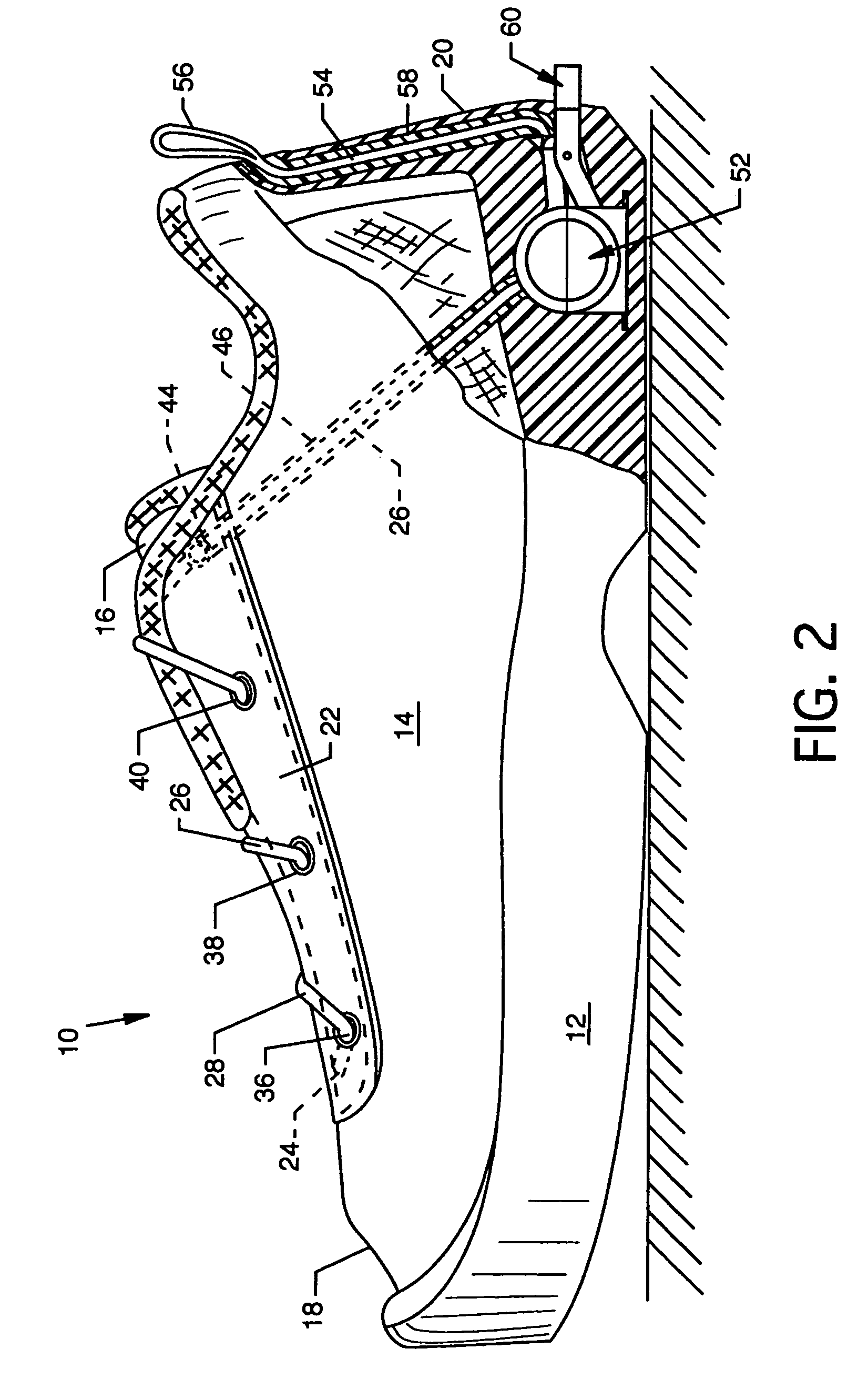
[0049]FIG. 1 illustrates a top view of an automated tightening shoe 10, the present invention, and FIG. 2 illustrates a side view, in partial cutaway, of the automated tightening shoe 10.

[0050] The automated tightening shoe 10, as illustrated, is a sport or athletic shoe having a sole 12, an integral body member or shoe upper 14 including a tongue 16, a toe 18, a heel 20, and a reinforced lacing pad 22, all constructed of any common sport or athletic shoe materials. An anchoring fixture 24, which could be a loop or other geometric configuration, and which could be fabric, leather, plastic, metal, cloth or other suitable material, suitably secures to the forward regions of juncture of the tongue 16 and the reinforced lacing pad 22 to secure or anchor one end of each of the opposed shoe laces26 and 28, preferably having a round cross section, but alternatively having a flat cross section. Preferably, the shoe laces 26 and 28 then mutually crisscross over the tongue 16 and pass throug...


PUM

PropertyMeasurementUnit
tensionaaaaaaaaaa
reverse movementaaaaaaaaaa
rotationaaaaaaaaaa

Abstract

An automated tightening shoe where a tightening mechanism is actuated which operates in one direction to cause automatic tightening of the shoe about a wearer's foot and which releases to allow loosening of the shoe. Shoe laces are led to the interior of the tightening mechanism in the heel whereat the laces are operatively associated in a tightening or in a loosening direction with the tightening mechanism. The tightening mechanism includes a rotatable central shaft which may have drums mounted thereto, a ratcheted coupling collar or ratcheted cam disk, a ratcheted actuator spool, a compression spring, a return spring, a ratchet wheel, and a release lever including a pawl and a cam actuator bar, all of which extend along the central shaft and operate to tighten as well as to allow loosening of the shoe laces.

Description

CROSS REFERENCES TO RELATED APPLICATIONS [0001] This patent application is a continuation-in-part of Ser. No. 10 / 093,918 entitled “Automated Tightening Shoe” filed on Mar. 7, 2002, pending, which is a divisional of Ser. No. 09 / 675,607 entitled “Automated Tightening Shoe” filed on Sep. 29, 2000, U.S. Pat. No. 6,467,194, which is a continuation-in-part of Ser. No. 09 / 048,772 entitled “Automated Tightening Shoe” filed Mar. 26, 1998, now abandoned, all by the same inventor.BACKGROUND OF THE INVENTION [0002] 1. Field of the Invention [0003] The present invention pertains to a shoe and, more particularly, to an automated tightening shoe. The shoe is provided with an automated tightening system including a tightening mechanism which operates in one direction to cause automatic tightening of the shoe about a wearer's foot, and which can be released easily so that the shoe can be readily removed from the wearer's foot. The invention is chiefly concerned with an automated tightening shoe of t...

Claims


Application Information

Patent Timeline
Patent Type & Authority Applications(United States)
IPC IPC(8): A43B11/00A43C7/00A43C11/00
CPCA43B11/00A43C7/00Y10T29/49838A43C11/008A43C11/165A43C11/00
Inventor JOHNSON, GREGORY G.
Owner HANDS FREE ENTERPRISES LLC
Why Eureka
Try Eureka