Cyclone dust-separating apparatus

a technology of dust separation apparatus and cyclone, which is applied in the direction of separation process, filtration separation, auxillary pretreatment, etc., can solve the problems of deterioration of separation efficiency, spillage of dust collected therein, and complicated structure, and achieve the effect of preventing the backflow of collected dus

Active Publication Date: 2006-07-20
SAMSUNG GWANGJU ELECTRONICS CO LTD
View PDF6 Cites 94 Cited by
  • Summary
  • Abstract
  • Description
  • Claims
  • Application Information

AI Technical Summary

Benefits of technology

[0009] The present invention has been developed in order to solve the above problems in the related art. Accordingly, an aspect of the present invention is to provide a cyclone dust-separating apparatus capable of preventing backflow of collected dust when a vacuum cleaner is overturned.
[0010] Another aspect of the present invention is to provide a cyclone dust-separating apparatus having a cover of a simplified construction.
[0011] The above aspects are achieved by providing a cyclone dus

Problems solved by technology

In this case, collected dust may be scatted or flow back to a discharge pipe by a cyclone air current, which causes deterioration of separation efficiency.
Scattered dust clogs a filter such as a discharge filter, and this becomes more problematic when a vacuum cleaner is overturned and thus dust collected therein spills.
However, when the canister type cleaner employing the cyclone dust-

Method used


Image

  • Cyclone dust-separating apparatus
  • Cyclone dust-separating apparatus
  • Cyclone dust-separating apparatus

Examples


Embodiment Construction

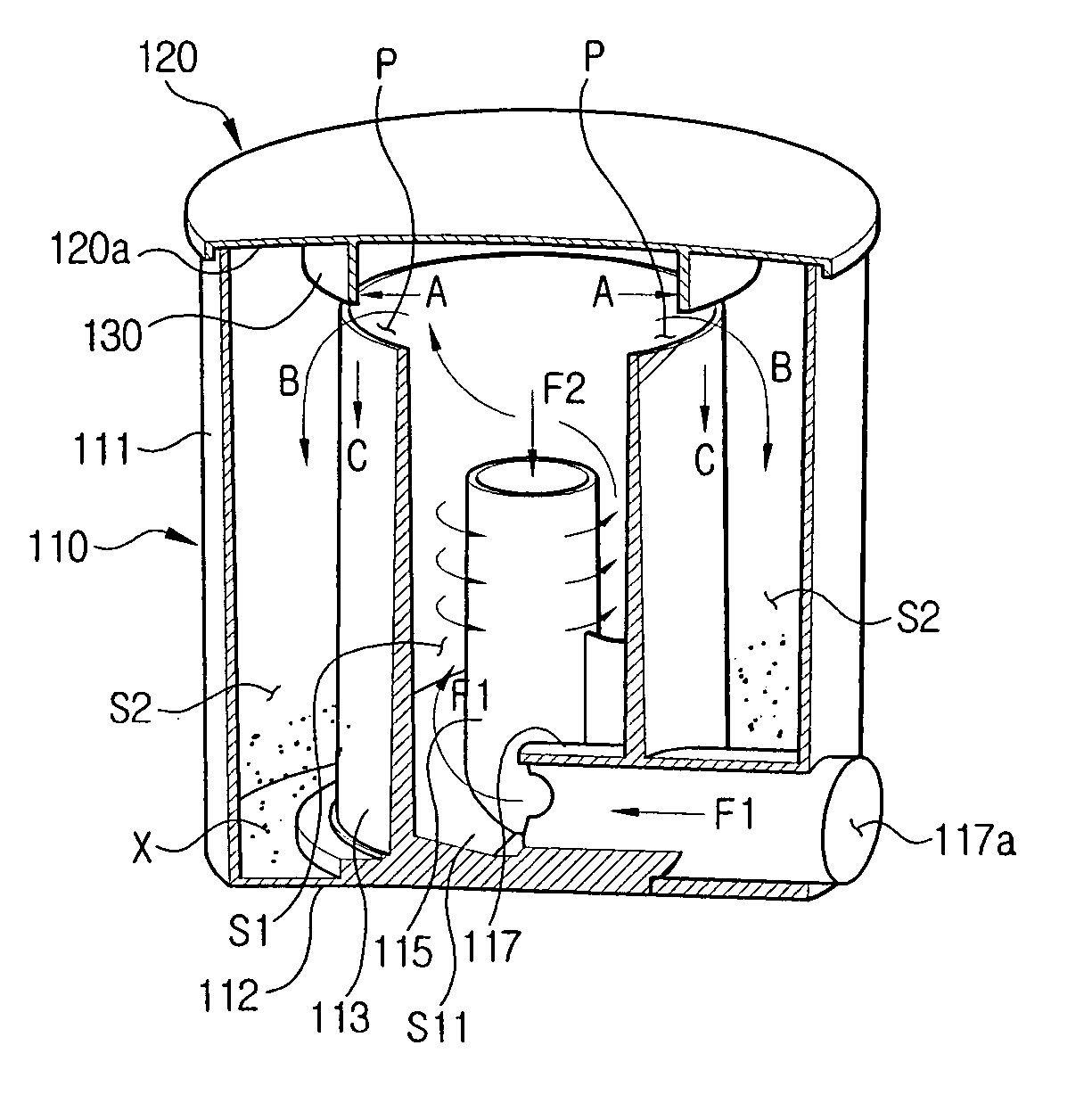
[0024] Hereinafter, a cyclone dust-separating apparatus according to an embodiment of the present invention will now be described in greater detail with reference to the accompanying drawings.

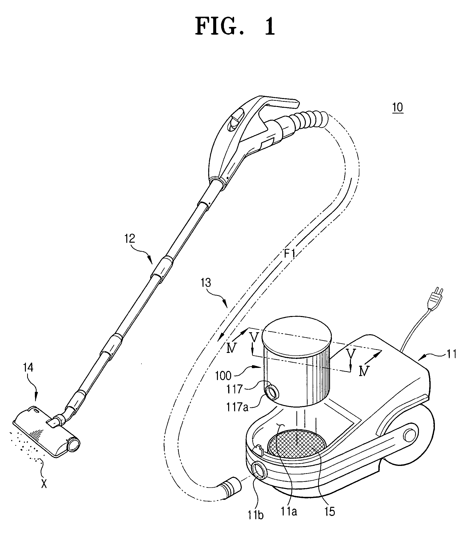
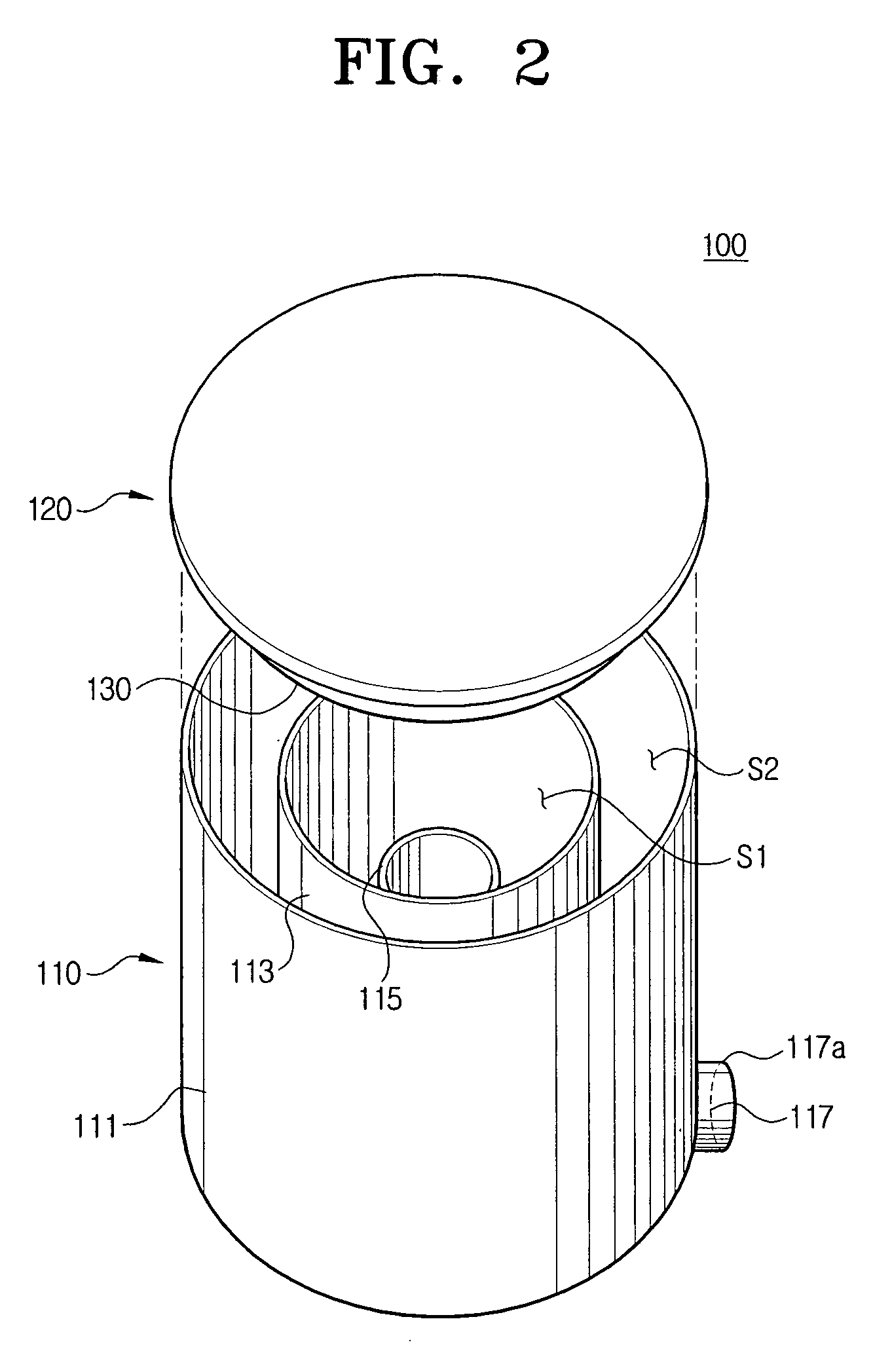
[0025]FIG. 1 illustrates a vacuum cleaner 10 employing a cyclone dust-separating apparatus 100 according to an exemplary embodiment of the present invention. The vacuum cleaner 10 has a cleaner body 11, an extension pipe 12, a flexible hose 13 (illustrated in phantom), a suction brush 14 connected to the cleaner body 11 through the extension pipe 12 and the flexible hose 13, and the cyclone dust-separating apparatus 100 removably mounted in the cleaner body 11.

[0026] A connection hole 11b is formed on a front surface of the cleaner body 11 to fluidly communicate with an air suction port 117a of the cyclone dust-separating apparatus 100. During assembly of vacuum cleaner 10, the flexible hose 13 is inserted into the connection hole 11b.

[0027] The cleaner body 11 is provided with a dust-collec...


PUM

PropertyMeasurementUnit
Diameteraaaaaaaaaa
Heightaaaaaaaaaa
Distanceaaaaaaaaaa

Abstract

A cyclone dust-separating apparatus including a cyclone body having a cyclone chamber and a dirt-collecting chamber enclosing an outer circumference of the cyclone chamber, an upper cover disposed on an upper end of the cyclone body to form a connection passage between the cyclone chamber and the dirt-collecting chamber, and a backflow prevention protrusion formed on an inner wall of the upper cover, for preventing dirt collected in the dirt-collecting chamber from flowing back to the cyclone chamber.

Description

CROSS-REFERENCE TO RELATED APPLICATIONS [0001] This application claims the benefit under 35 U.S.C. § 119(a) of Korean Patent Application No. 2005-03688, filed on Jan. 14, 2005, in the Korean Intellectual Property Office, the disclosure of which is incorporated herein by reference in its entirety. BACKGROUND OF THE INVENTION [0002] 1. Field of the Invention [0003] The present invention relates to a cyclone dust-separating apparatus employed in a vacuum cleaner, for centrifugally separating dust from drawn-in air. [0004] 2. Description of the Related Art [0005] An early model cyclone dust-separating apparatus, which is disclosed in U.S. Pat. No. 6,003,196, performs separating and collecting operations at the same place. In this case, collected dust may be scatted or flow back to a discharge pipe by a cyclone air current, which causes deterioration of separation efficiency. Scattered dust clogs a filter such as a discharge filter, and this becomes more problematic when a vacuum cleaner...

Claims


Application Information

Patent Timeline
IPC IPC(8): B01D45/12
CPCA47L9/1608A47L9/165A47L9/1658A47L9/1683B04C5/14B04C5/185Y10S55/03A47L9/16
Inventor KIM, TAK-SOO
Owner SAMSUNG GWANGJU ELECTRONICS CO LTD
Why Eureka
Try Eureka