Stirling engine having slidable piston

a piston and crankcase technology, applied in the field of crankcase engines, can solve the problems of inefficiency of engines and complex components, and achieve the effects of low cost, high volumetric efficiency, and easy manufacturing

Inactive Publication Date: 2006-07-20
DIETER ROBERT L
View PDF10 Cites 0 Cited by
  • Summary
  • Abstract
  • Description
  • Claims
  • Application Information

AI Technical Summary

Benefits of technology

[0004] The present invention is a rotary Stirling cycle engine. The engine is compact, lightweight and easy to manufacture. The engine has a rotor and a slidable piston that are contained within a stator. The resulting engine is compact, light weight and high in volumetric efficiency. Since the motion is rotary, the engine operates with little noise or vibration. The engine is capable of using a wide variety of fuels including conventional, low volatility, geothermal, solar and waste heat.

Problems solved by technology

Others require heat regenerators, and have complex components that are often expensive to produce.
Heat loss in these engines is frequently high, and therefore, the engine is inefficient.

Method used


Image

  • Stirling engine having slidable piston
  • Stirling engine having slidable piston
  • Stirling engine having slidable piston

Examples


Embodiment Construction

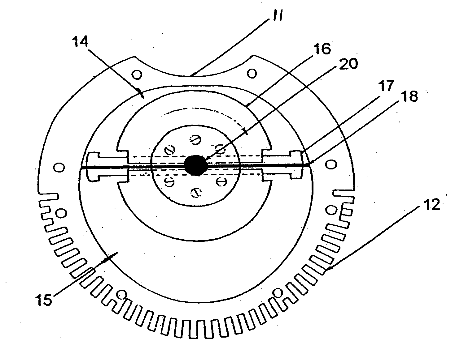
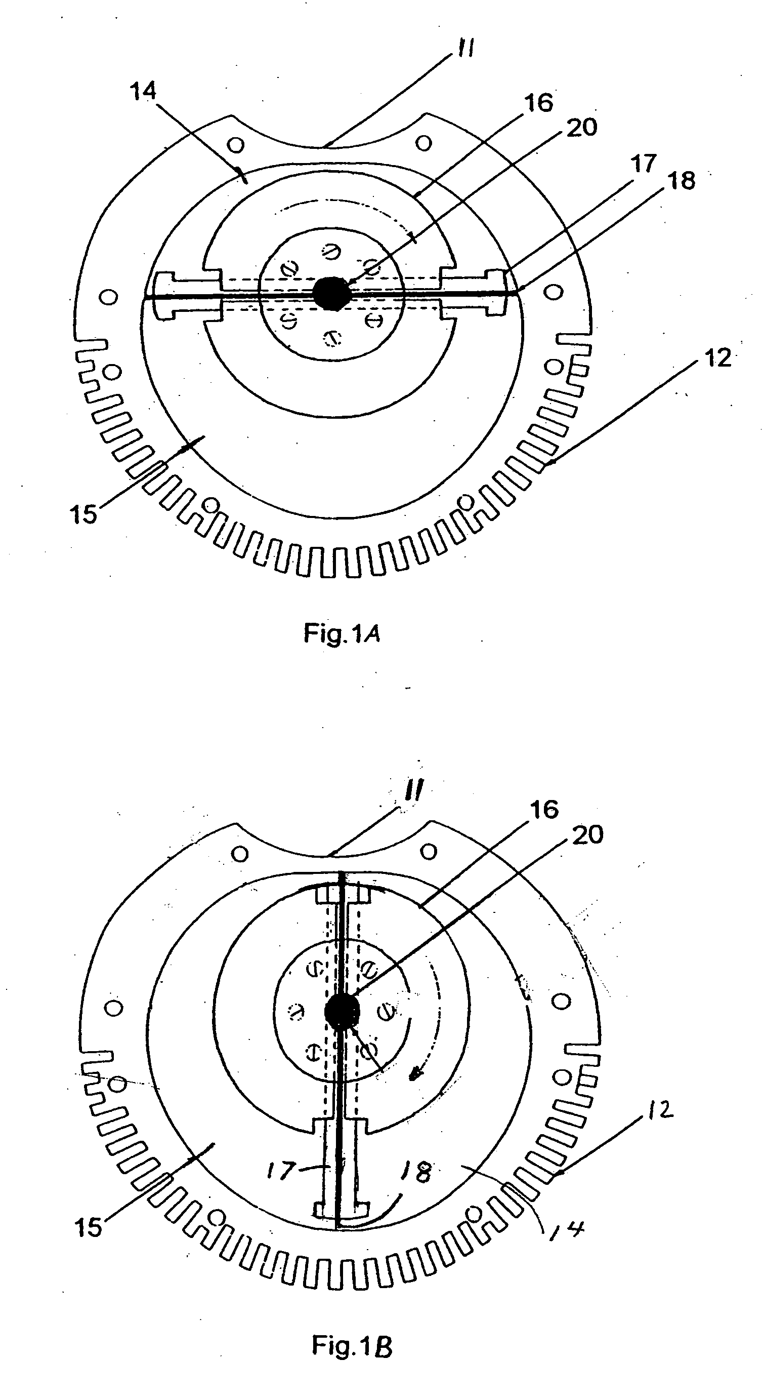
[0010] In the preferred embodiment, the engine has a stator 10, a rotor 16 and a slidable piston 17 that slides within the rotor. FIG. 1A and FIG. 1B. The stator 10 is preferred to have an irregular, and annular, generally cylindrical chamber in which the rotor rotates. The diameter of the annular chamber, when taken from any direction though the axis of rotation of the rotor, is constant, subject to reasonable manufacturing tolerances. The annular chamber is not circular where the rotor rotates within the chamber, as demonstrated by the sectional views of FIG. 1A and FIG. 1B.

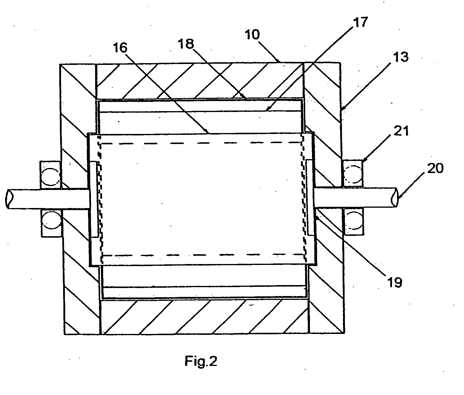
[0011] The rotor 16 is mounted axially, and the center of rotation is offset from the center of the chamber, so that the axis of rotation of the rotor is not in the center of the chamber. The rotor may be circular when viewed as in FIG. 1A, or have an overall generally cylindrical shape, FIG. 2.

[0012] Slidable piston 17 is positioned within the rotor. The slidable piston is fitted with seals 18 and is slidabl...


PUM


Abstract

The present invention is a rotary engine having a rotor and a slidable piston that are contained within a stator.

Description

[0001] Applicant claims the benefit of Provisional Application Ser. No. 60 / 644,472 filed Jan. 14, 2005FIELD OF THE INVENTION [0002] This invention relates to engines. BACKGROUND OF THE INVENTION [0003] Most existing Stirling cycle engines rely on reciprocating pistons, connecting rods and crankshaft systems. Others require heat regenerators, and have complex components that are often expensive to produce. Heat loss in these engines is frequently high, and therefore, the engine is inefficient. SUMMARY OF THE INVENTION [0004] The present invention is a rotary Stirling cycle engine. The engine is compact, lightweight and easy to manufacture. The engine has a rotor and a slidable piston that are contained within a stator. The resulting engine is compact, light weight and high in volumetric efficiency. Since the motion is rotary, the engine operates with little noise or vibration. The engine is capable of using a wide variety of fuels including conventional, low volatility, geothermal, s...

Claims


Application Information

Patent Timeline
Patent Type & Authority Applications(United States)
IPC IPC(8): F02G1/04F01B29/10
CPCF02G1/053F02G2270/10
Inventor DIETER, ROBERT L.
Owner DIETER ROBERT L
Why Eureka
Try Eureka