
Cycloidal Pinwheel Pair with Uniform Contact and One-tooth Difference

a technology of cycloid pinwheel and uniform contact, which is applied in the direction of liquid fuel engines, machines/engines, rotary piston liquid engines, etc., can solve the problems of significant affecting the working stability of hydraulic equipment, reducing complex structure, so as to improve volume efficiency and mechanical efficiency, improve manufacturability, and improve the effect of volume efficiency

Inactive Publication Date: 2015-02-19
ZHENJIANG DALI HYDRAULIC MOTOR
View PDF5 Cites 0 Cited by
  • Summary
  • Abstract
  • Description
  • Claims
  • Application Information

AI Technical Summary

Benefits of technology

The present disclosure provides a new design for a cycloidal pinwheel pair that can improve the efficiency of hydraulic components. The design has a simple structure and is easy to manufacture. It also prevents internal leakage and improves the volume and mechanical efficiency of the components. This is achieved by creating a transition chamber between high and low pressure chambers using a modified recess. Additionally, an oil film is formed which reduces friction, improves flexibility, and reduces the requirement for machining precision.

Problems solved by technology

However, since machining errors and position errors exist in mechanical parts, a certain clearance has to be reserved in design to compensate the errors afore-mentioned; therefore, every independent chamber is sealed by oil film in actual.
In situations of heavy load or large torque transmission, the above mentioned errors and the reserved clearance may cause internal leakage of the cycloidal meshing pair (such as the hydraulic motor), which significantly affects the working stability of hydraulic equipment such as the hydraulic motor, and reduces the volume efficiency and mechanical efficiency.
However, this technical solution employs too many concave segments, as a result, it is complex in structure, tedious in design and calculation, and difficult to produce.

Method used


Image

  • Cycloidal Pinwheel Pair with Uniform Contact and One-tooth Difference
  • Cycloidal Pinwheel Pair with Uniform Contact and One-tooth Difference
  • Cycloidal Pinwheel Pair with Uniform Contact and One-tooth Difference

Examples


embodiment

[0026 one:

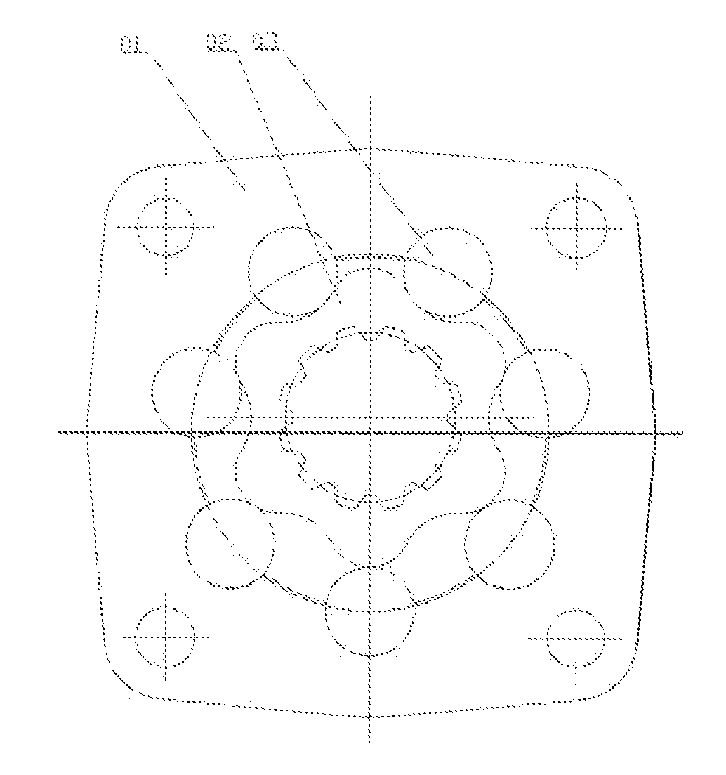
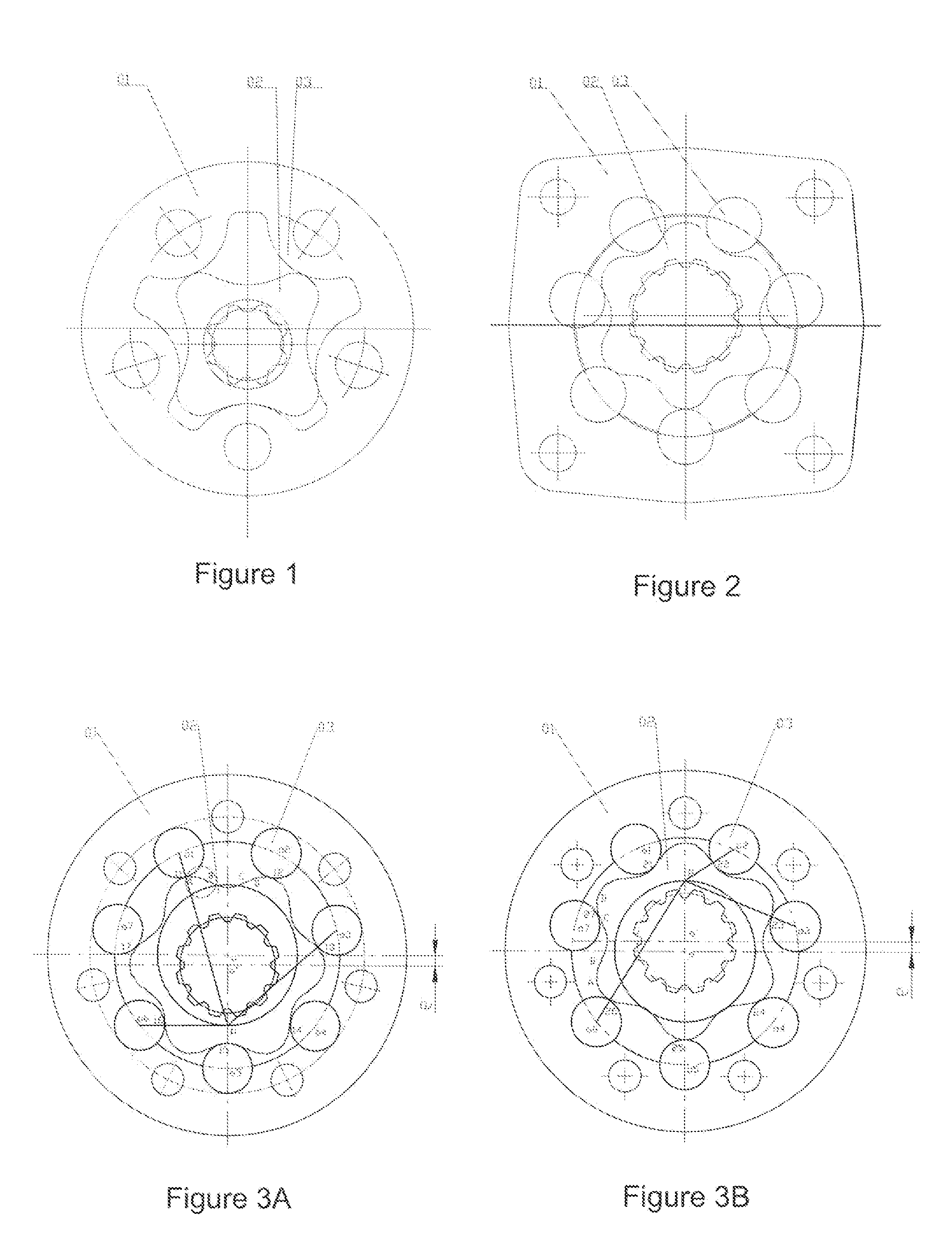
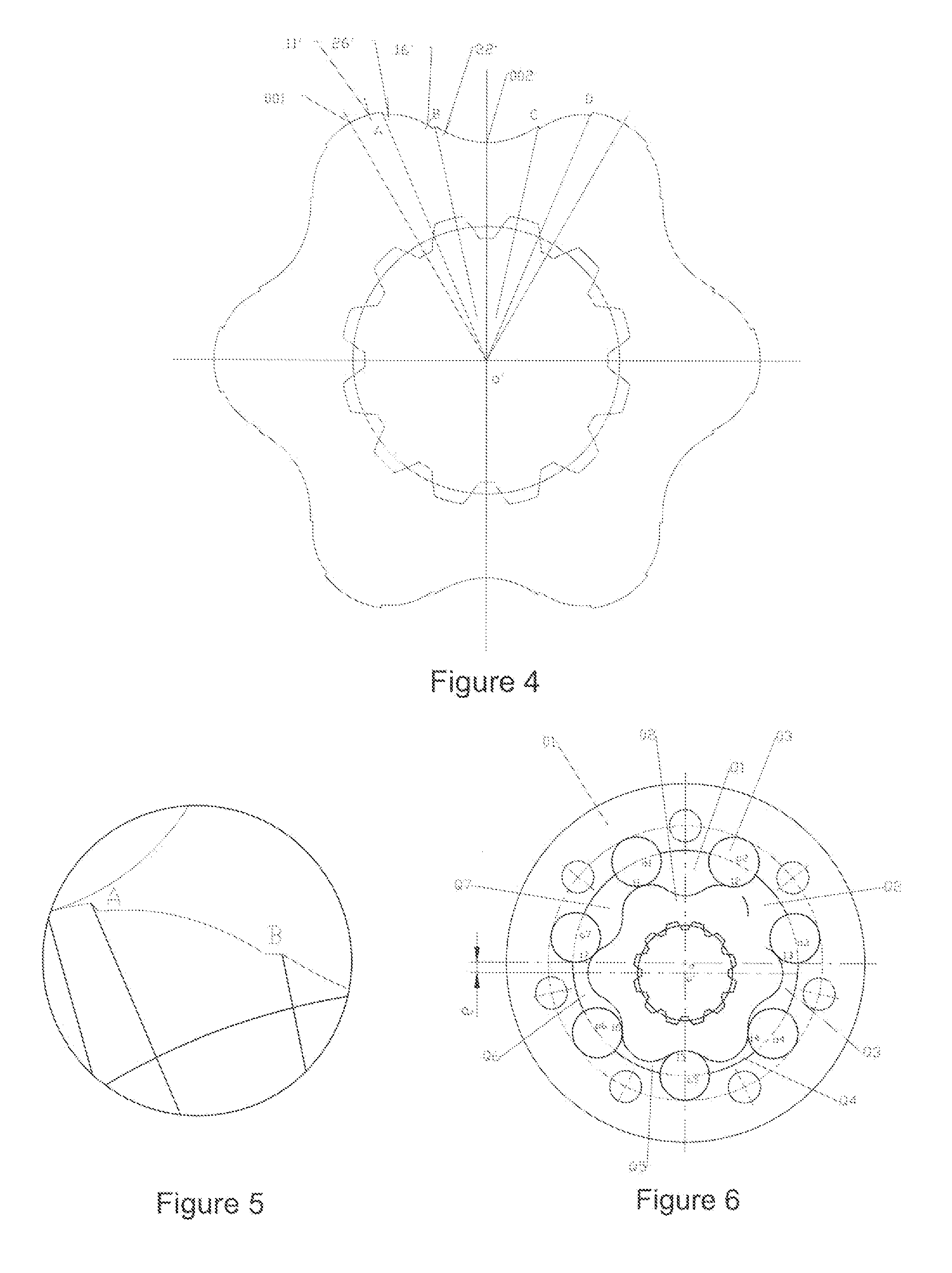
[0027]The structure of the cycloidal pinwheel pair with uniform contact and one-tooth difference according to embodiment one is as shown in FIG. 3A and FIG. 3B, including the stator 01 having seven pin teeth 03 in interval distribution, and the pinwheel rotor 02 having six gear teeth meshing with the stator, the centers of the seven pin teeth respectively are o1, o2, o3, o4, o5, o6 and o7. The meshing instant center P is the meshing pitch point formed by the rotor and the pin teeth, and is also the intersection point of the connection lines respectively formed between each of pin tooth centers o1, o2, o3, o4, o5, o6 and o7, and the respective meshing contact points 11, 12, 13, 14, 15, 16 and 17 of the gear teeth. Each gear tooth profile of the pinwheel rotor has a modified recess provided symmetrically on both sides (as shown in FIG. 4).

[0028]As shown in FIG. 4, the starting point A of the modified recess on one side of the gear tooth profile is located between the first p...


PUM


Abstract

Disclosed is a cycloidal pinwheel pair with uniform contact and one-tooth difference, comprising a stator and a rotor. Each gear tooth profile of the rotor has a modified recess provided symmetrically on both sides; the starting point (A) of the modified recess on one side of the gear tooth profile is located between a first point and a second point determined by locations of two limit positions, the end point (B) of the modified recess on the same side of the gear tooth profile is located between a third point and a fourth point determined by locations of two limit positions. By adopting the present disclosure, the internal leakage formed between high and low pressure chambers is effectively avoided, thereby significantly improving the volume efficiency and mechanical efficiency. Meanwhile, the present disclosure is extremely simple in structure and can be molded by one-time grinding with better manufacturability.

Description

CROSS-REFERENCE TO RELATED APPLICATIONS[0001]This application claims priority to Chinese Application No. 201110378546.7, “Cycloidal Pinwheel Pair with Uniform Contact and One-tooth Difference”, filed on Nov. 24, 2011, which is hereby incorporated by reference in its entirety.TECHNICAL FIELD[0002]The present disclosure relates to a cycloidal pinwheel pair, and more particularly to a cycloidal pinwheel pair with uniform contact and one-tooth difference, belonging to the technical fields of cycloidal hydraulic motors and fully hydraulic diverters.BACKGROUND ART[0003]A cycloidal pinwheel pair with one-tooth difference has advantages such as compact structure, high kinematic precision, low noise, high tooth strength, strong bearing capacity, little junction surface friction, high transmission efficiency, higher power density, and so on. Therefore, it is widely used in products such as cycloid hydraulic motors with large torque and low speed, fully hydraulic diverters, cycloid pumps, and ...

Claims


Application Information

Patent Timeline
Patent Type & Authority Applications(United States)
IPC IPC(8): F04C2/10F04C18/10
CPCF04C18/10F04C2/10F04C2/084F04C2/103F03C2/08
Inventor WANG, ZHISHENGWENG, AIGUANGZHANG, ZHIMINJI, LIQUNLOU, FENG
Owner ZHENJIANG DALI HYDRAULIC MOTOR
Learn More