Holder with V-knife blade for bi-directional rupture disc assembly

a technology of rupture discs and blades, which is applied in the direction of functional valve types, transportation and packaging, containers, etc., can solve the problems of inability to open discs, inconvenient shutdown of vessels, and inability to meet the requirements of the overall manufacturing process, so as to achieve more reliable and consistent rupture and reduce pressur

Active Publication Date: 2006-07-20
FIKE CORP
View PDF12 Cites 7 Cited by
  • Summary
  • Abstract
  • Description
  • Claims
  • Application Information

AI Technical Summary

Benefits of technology

[0009] The present invention relates to a rupture disc holder member especially useful for sanitary applications and that provides for more reliable and consistent severing and fuller opening of a bi-directional rupture disc and especially at lower pressures when the disc reverses under a vacuum condition and is deflected against a disc cutting element mounted in the holder, than prior holders employing a welded three-blade configuration. A generally V-shaped cutting element for the disc is mounted in the disc holder and has a pair of elongated leg components connected to and supported by the interior wall surface of the holder. The leg components extend inwardly from the holder member wall surface, converge toward one another, and join at their innermost extremities. The V-shaped cutting element is of one-piece construction, thereby eliminating the problems associated with required welding of adjacent tri-knife blades. The innermost extremities of the leg components define a cutting edge located to engage and sever the disc when the disc is deflected and reverses, even under a relatively low-level vacuum condition.
[0010] The leg components of the cutting element are located in a position defining an angle therebetween of approximately 120°. This widely spread leg arrangement of the leg components of the cutting element assures that the separate segments of the Teflon bi-directional rupture disc, upon severing, pass cleanly through the two areas on opposite sides of the cutting element without a tendency to hang up on the cutting element, especially at the joinder area of the converging leg segments of the cutting element.

Problems solved by technology

This is especially true in the pharmaceutical industry where the valuable content of a process vessel must be protected from cyclic vacuum conditions that could cause contamination of the contents of the vessel, or result in an expensive shutdown of the vessel and interfere with the overall manufacturing process.
These weld fillets are believed to be in part responsible for what is deemed to be the unacceptable failure rates of discs to open upon reversal and engagement with the tri-knife cutting member.

Method used


Image

  • Holder with V-knife blade for bi-directional rupture disc assembly
  • Holder with V-knife blade for bi-directional rupture disc assembly
  • Holder with V-knife blade for bi-directional rupture disc assembly

Examples


Embodiment Construction

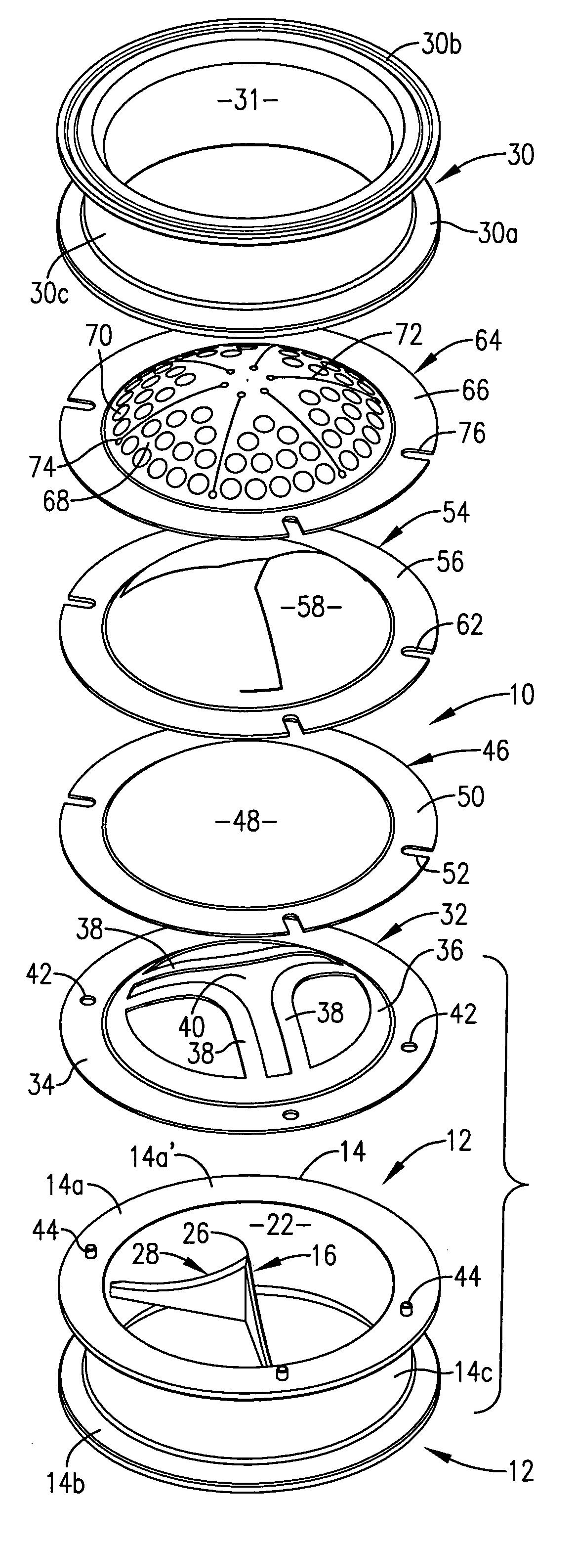
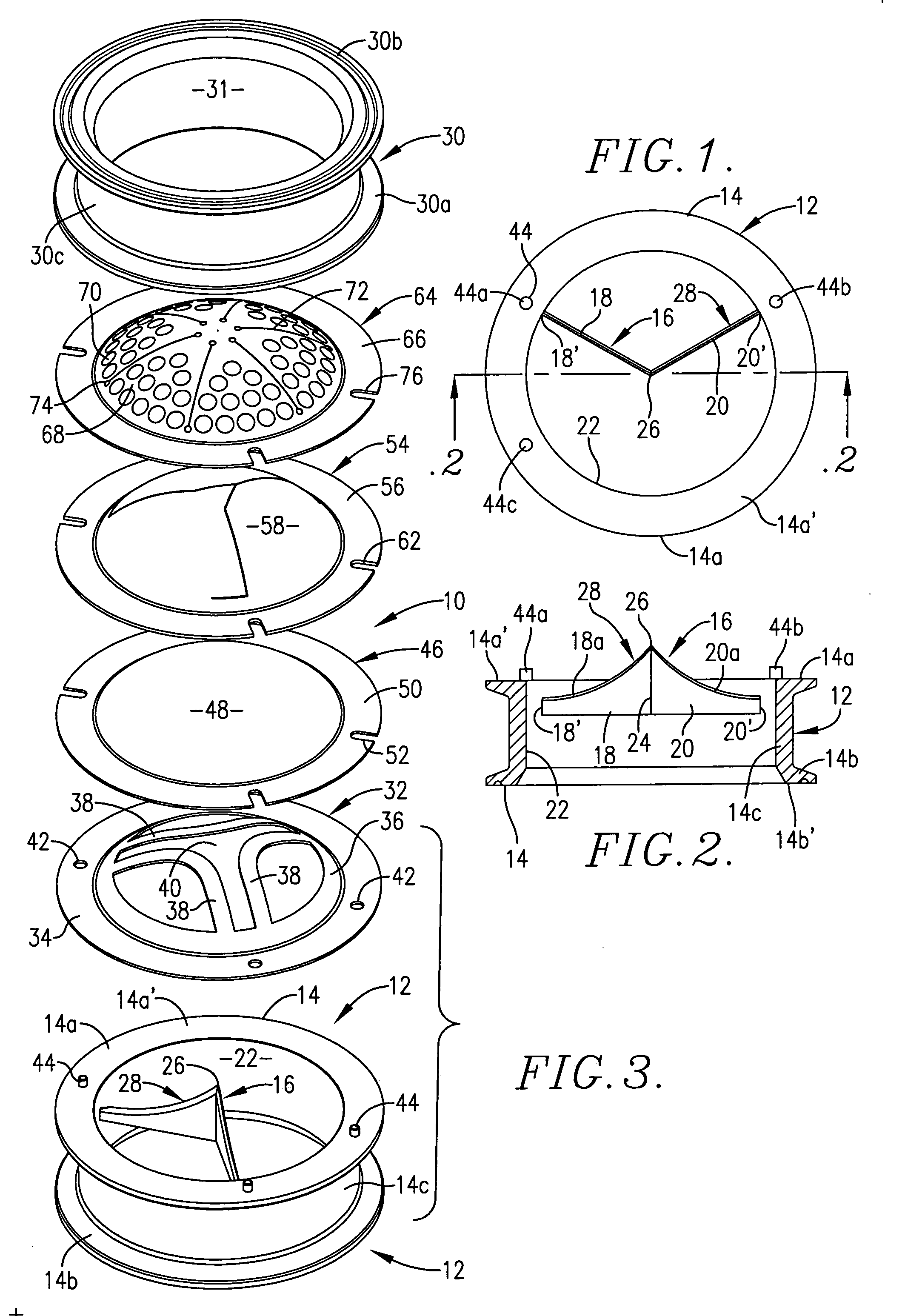
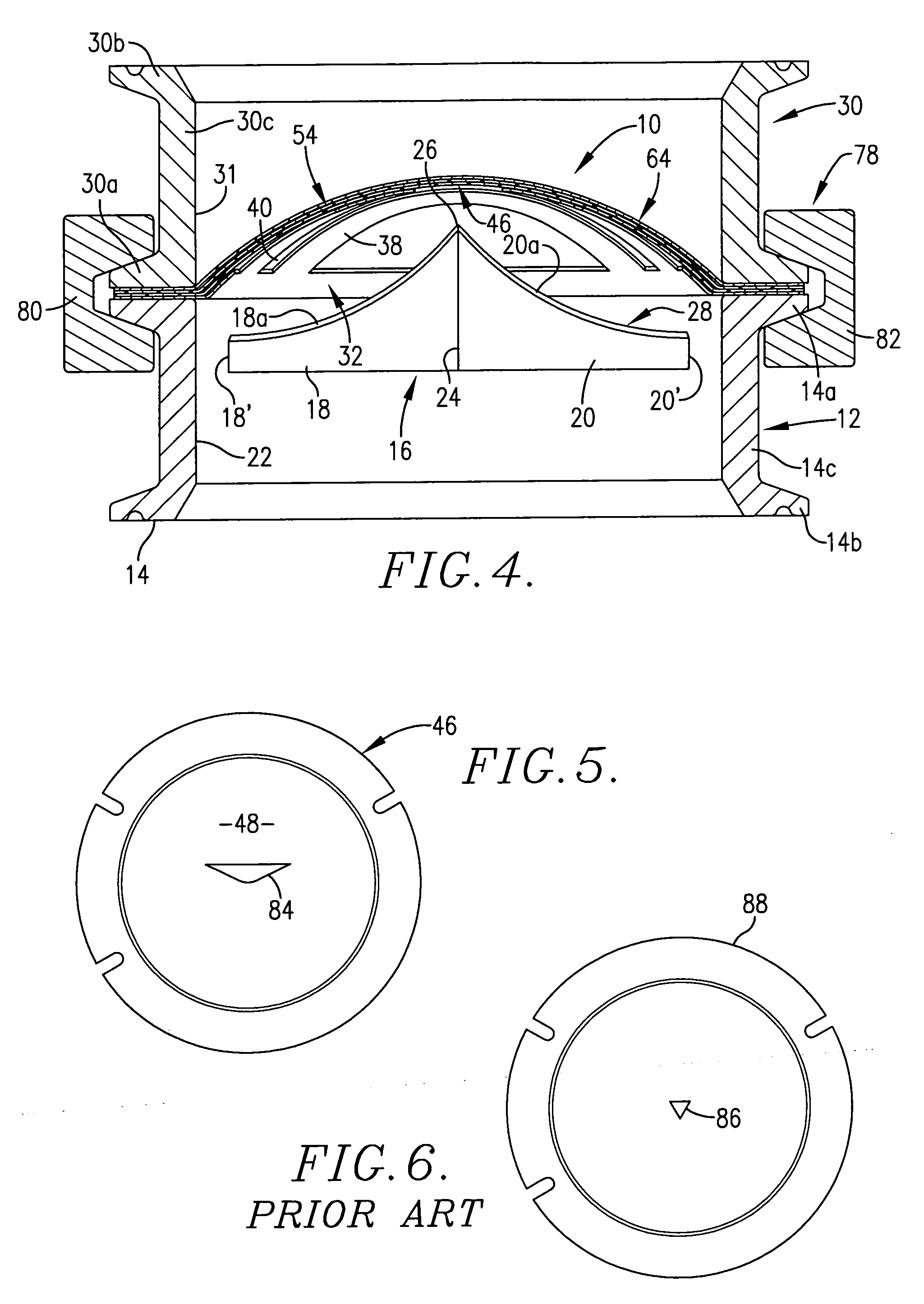
[0019] A pressure relief assembly 10 as shown in FIG. 4 is made up of the components more specifically illustrated in exploded view FIG. 3. Assembly 10 includes a holder member 12 that, for example, may comprise a holder support body 14 having a pair of spaced circular flange segments 14a and 14b separated by a unitary, generally cylindrical central hub section 14c. It can be seen from FIGS. 2 and 4 that the flange segments 14a and 14b are of greater diameter than the hub section 14c. A V-shaped cutting element 16 is provided within the cylindrical interior of holder support body 14. The terminology V-shaped cutting element 16 as used herein means that the cutting element is of V-shaped configuration in plan view.

[0020] The V-shaped cutting element 16 has a pair of elongated leg components 18 and 20 with the outermost margins 18′ and 20′ of components 18 and 20 being rigidly affixed to the inner cylindrical wall surface 22 of holder member 12 below the annular margin 14a′ of flange...


PUM


Abstract

This invention relates to a cylindrical holder member for a bi-directional bulged rupture disc. The support body of the holder has a rim that supports the rupture disc with the concave surface of the disc facing the holder. The support body is provided with a unitary one-piece, centrally creased cutting element that is of generally V-shaped configuration in plan view. The cutting element has a pair of elongated converging leg components with each leg component being connected to and supported by the interior wall surface of the holder body, with each leg component having an arcuate cutting edge. The cutting edges of the leg components merge at the crease in the cutting element to define a central cutting edge peak section. The cutting element is positioned in the holder with the cutting edge peak section extending beyond the rim of the support body into the concave area of the disc. The V-shaped cutting element functions to provide for a fuller and more rapid opening of the disc upon reversal and engagement with the cutting element as compared with prior reverse buckling disc three-knife blade cutter units. The invention has especial utility in food, beverage, and pharmaceutical applications requiring sanitary pressure relief rupture disc structure.

Description

BACKGROUND OF THE INVENTION [0001] 1. Field of the Invention [0002] The present invention relates generally to a rupture disc assembly having a bi-directional, concavo-convex rupture disc and a support body for the rupture disc that is provided with a generally V-shaped cutting element in plan view and disposed to engage and sever the disc when the disc is deflected toward the cutting element. The cutting element has a pair of leg components that are connected to the interior wall surface of the support body and that converge and join at their innermost extremities. In particular, the V-shaped cutting element is of one-piece construction with the central V-shaped cutting edge section of the cutting element defined by a unitary crease in the cutting element being positioned to extend into the concave portion of the rupture disc. The cutting edge of the cutting element includes cutting edge segments that extend along the full length of each of the leg components of the cutting element...

Claims


Application Information

Patent Timeline
Patent Type & Authority Applications(United States)
IPC IPC(8): F16K17/40
CPCF16K17/1613Y10T137/1699Y10T137/1759
Inventor KREBILL, MICHAEL D.O'HALLORAN, DANIEL G.FARNSWORTH, JEROMIE T.STILWELL, BRADFORD T.
Owner FIKE CORP
Why Eureka
Try Eureka