
Molding method of plastic materials

a plastic material and molding technology, applied in the field of molding methods of plastic materials, can solve the problems of difficult narrowing of the infrared irradiation area and long heating time of plastic materials, and achieve the effects of accurate irradiation to plastic materials, good transparency to visible light, and effective heating of infrared

Inactive Publication Date: 2006-07-20
FUJIFILM HLDG CORP +1
View PDF6 Cites 10 Cited by
  • Summary
  • Abstract
  • Description
  • Claims
  • Application Information

AI Technical Summary

Benefits of technology

[0016] As described above, in the plastic molding method of the present invention, laser or focused infrared is irradiated to the plastic material. An irradiation area of the infrared can easily be controlled since the infrared is not diffused. Through this process, since the infrared can be accurately irradiated to the plastic material, the plastic material can be effectively heated up with the infrared within a short time.
[0034] According to the plastic molding method described in the above, the laser or the focused infrared can be accurately irradiated to the plastic material by easily controlling the infrared irradiation area. As a result, the plastic material can be efficiently heated up by the laser or the focused infrared within a short time, thereby resulting in increasing a manufacturing efficiency of products.

Problems solved by technology

However, in the above manufacturing method, since the infrared is diffusely irradiated from the infrared panel heater, it is difficult to narrow an irradiation area of the infrared.
As understood from the above, since a heating efficiency of the infrared panel heater is low, a heating time of the plastic material becomes long.

Method used


Image

  • Molding method of plastic materials
  • Molding method of plastic materials
  • Molding method of plastic materials

Examples


Embodiment Construction

[0046] Next, embodiment of the present invention will be explained in detail by referring to figures.

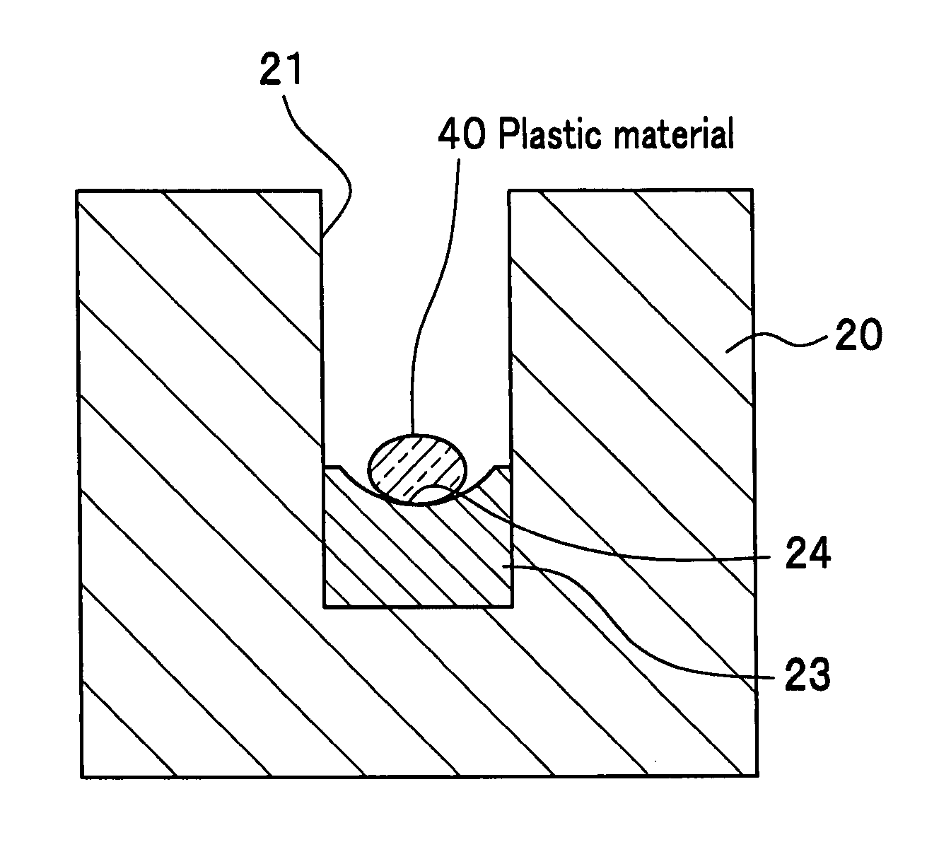
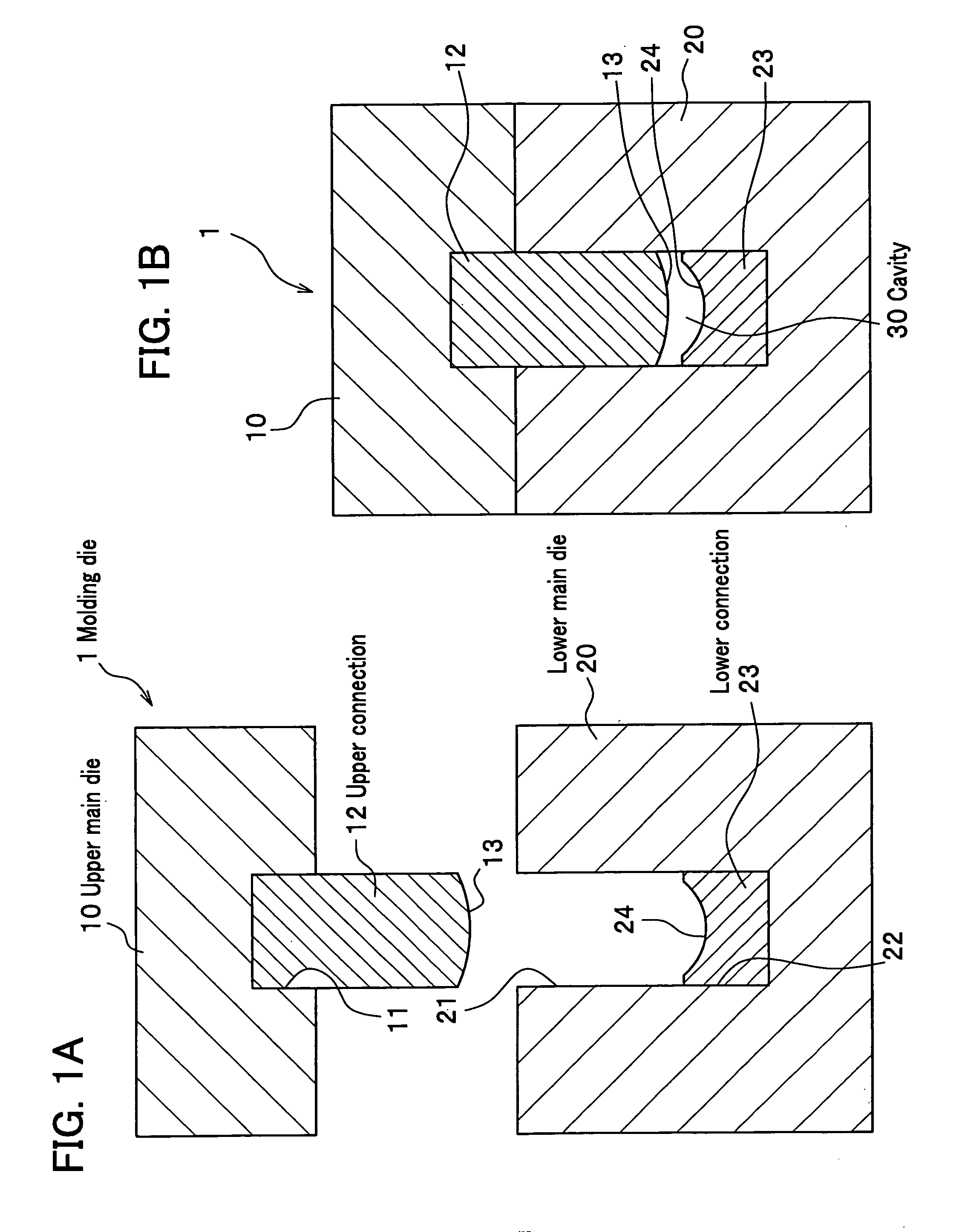
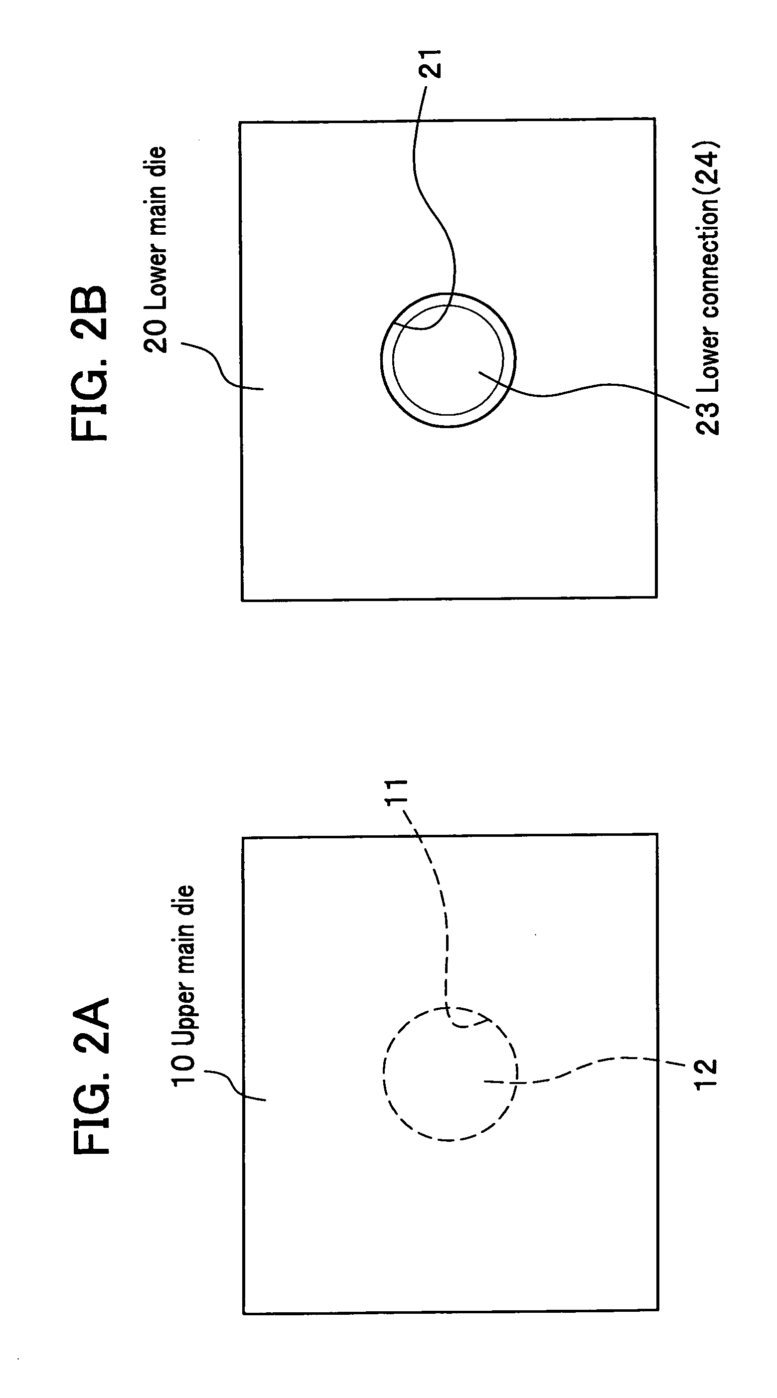
[0047]FIGS. 1A and 1B are views showing a molding die for a molding method of plastic material of the present embodiment. FIG. 1A is a side cross sectional view showing each main die being separated, and FIG. 1B is a side cross sectional view showing the each main die being engaged with. FIGS. 2A and 2B are views showing a molding die for a molding method of plastic material of the present embodiment. FIG. 2A is a plane view showing an upper main die, and FIG. 2B is a plane view showing a lower main die. FIG. 3 is a side cross sectional view showing a molding die, in which a light focusing unit is arranged between the main dies, for a molding method of plastic material of the embodiment.

[0048] In the present embodiment, an example for manufacturing a plastic lens with compression molding of a plastic material will be used for explaining the present invention.

(Configuration of Mol...


PUM

PropertyMeasurementUnit
diameteraaaaaaaaaa
diameteraaaaaaaaaa
oscillation wavelengthaaaaaaaaaa

Abstract

A plastic molding method comprising steps of heating a plastic material with irradiation of infrared laser or focused infrared to the plastic material put in a cavity of a molding die and compressing the plastic material within the cavity for deforming the plastic material into a given shape. The plastic material is a transparent material to visible light to which an infrared absorption material is added. The infrared laser is irradiated using a carbon dioxide gas laser unit. A water content of the plastic material is no more than 0.01% by mass. The irradiation of the infrared to the plastic material is implemented under atmosphere of an inert gas. The plastic material is any one of polycarbonate, polyester, cyclopolyolefin, acryl, alicyclic acryl resin, and olefin-maleimide-alternating-copolymer. Accordingly, the plastic material can be effectively heated up by the infrared within a short time, thereby resulting in increasing a manufacturing efficiency of products.

Description

CROSS REFERENCE TO RELATED APPLICATIONS [0001] This application claims the foreign priority benefit under Title 35, United States Code, §119(a)-(d) of Japanese Patent Applications No. 2005-010398 and 2005-118211, filed on Jan. 18, 2005 and Apr. 15, 2005, respectively, the contents of which are hereby incorporated by reference. BACKGROUND OF THE INVENTION [0002] 1. Technical Field of the Invention [0003] The present invention relates to a molding method of a plastic material for manufacturing a product with compression molding of the plastic material. [0004] 2. Description of the Related Art [0005] As a manufacturing method of a plastic lens using a plastic material, there is a method where the plastic lens is manufactured with compression molding of the plastic material within a cavity formed between each main die of a molding die by combining the each main die, that is, an upper main die and a lower main die arranged in upper and in lower positions, respectively. [0006] Here, in co...

Claims


Application Information

Patent Timeline
Patent Type & Authority Applications(United States)
IPC IPC(8): B29D11/00
CPCB29C43/00B29C43/021B29C43/52B29C2043/3618B29D11/00413B29L2011/0016
Inventor SUZUKI, FUMIYUKIMOCHIZUKI, TADASHI
Owner FUJIFILM HLDG CORP
Learn More