Brake fluid pressure control apparatus and method

a technology of brake fluid and control apparatus, which is applied in the direction of brake systems, etc., can solve the problems of increasing the pressure of the brake cylinder accordingly, and achieve the effects of reducing the control gain, reducing the rate, and reducing the degree of slipper with respect to the friction coefficient of the road surfa

Inactive Publication Date: 2006-07-20
TOYOTA JIDOSHA KK
View PDF10 Cites 15 Cited by
  • Summary
  • Abstract
  • Description
  • Claims
  • Application Information

AI Technical Summary

Benefits of technology

[0014] In a vehicle with a supple suspension, for example, when the operating force of the braking member is increased while the operating force is large, the front wheels are likely to slip by an excessively large degree due to a delay in the movement of the load toward the front wheels. If the control gain is reduced when there is a high possibility of excessively large slip (for example, when the operating force of the braking member is large), the actual brake cylinder pressure can be increased at a reduced rate, and the time at which the degree of slip becomes excessively large with respect to the coefficient of friction of the road surface can be delayed. The control gain may also be reduced when the operating force of the braking member is large AND the speed of the operation of the braking membe

Problems solved by technology

When the temperature of the working fluid is low, for example, the viscosity of the working

Method used


Image

  • Brake fluid pressure control apparatus and method
  • Brake fluid pressure control apparatus and method
  • Brake fluid pressure control apparatus and method

Examples


Embodiment Construction

[0032] A hydraulic brake system of a motor vehicle having a brake fluid pressure control apparatus as an exemplary embodiment of the invention will be described with reference to the drawings. The vehicle on which the hydraulic brake system of this embodiment is installed has a relatively large empty vehicle weight (and, therefore, large braking force appears in the vehicle), and has a relatively supple or soft suspension.

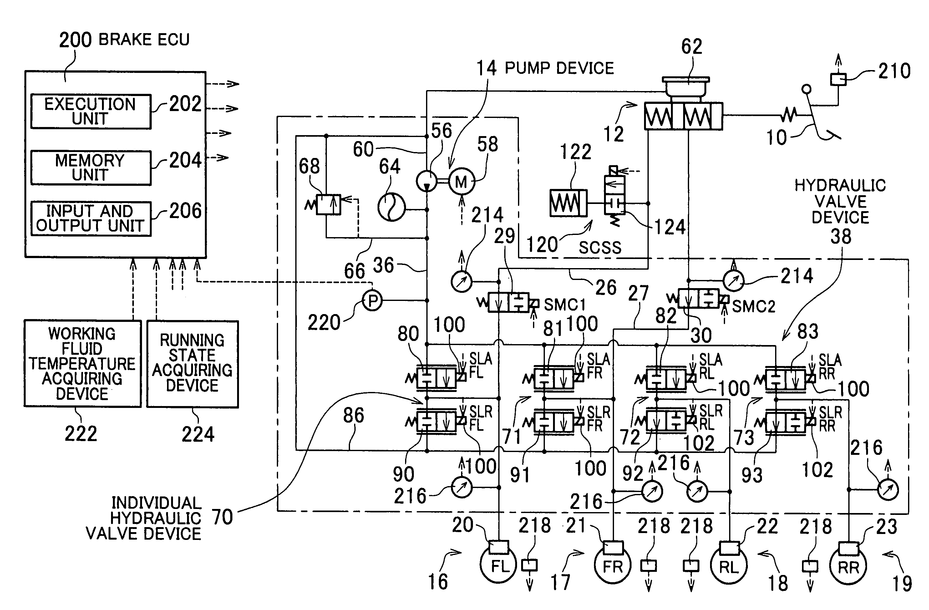
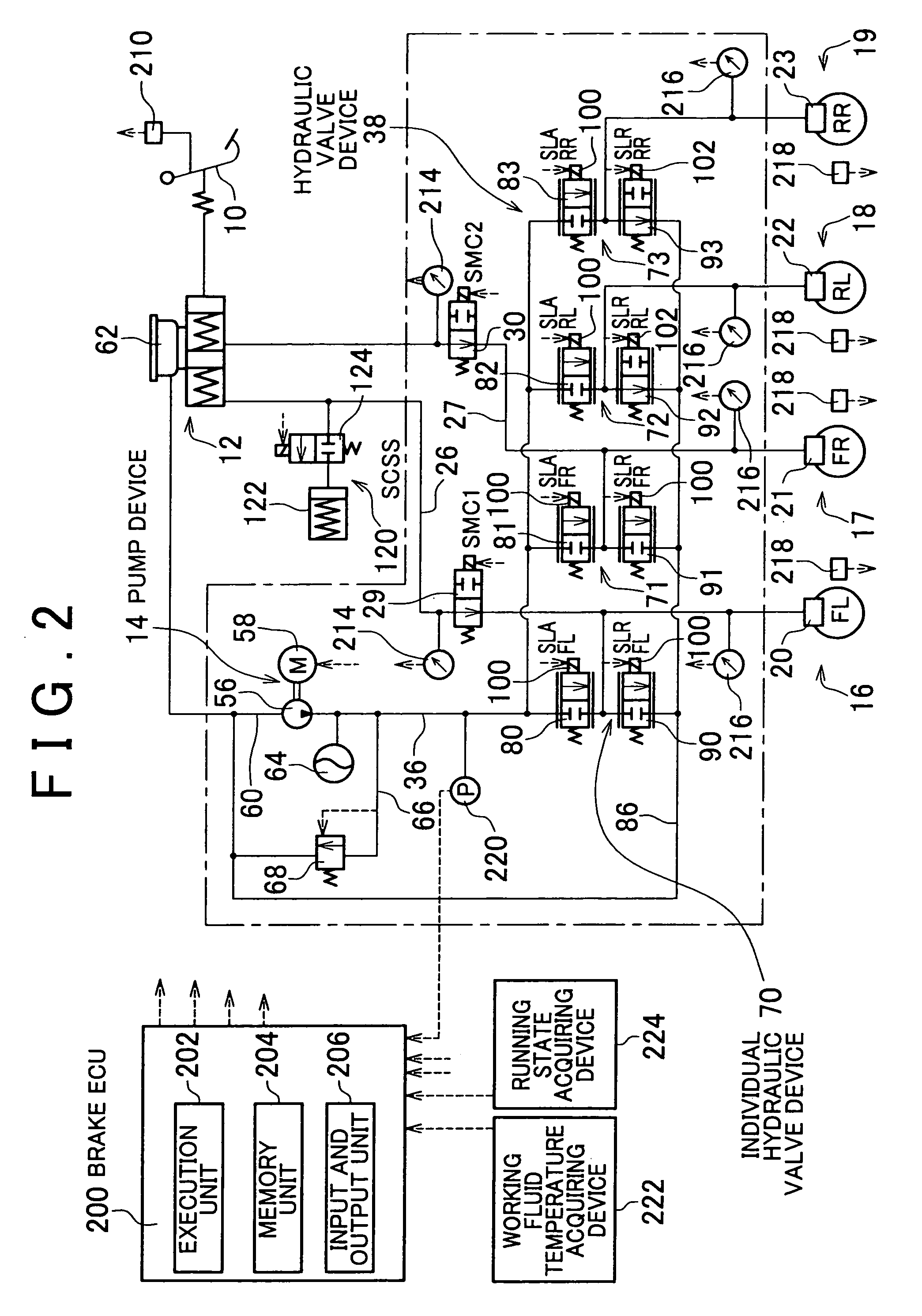
[0033] Referring to FIG. 2, the hydraulic brake system includes a brake pedal 10 that serves as a braking member, a master cylinder 12 having two pressure chambers, a pump device 14 that serves as a fluid pressure source operable by power, and hydraulic brakes 16, 17, 18, 19 provided for the respective wheels located on the front-left, front-right, rear-left and rear-right sides of the vehicle. The hydraulic brakes 16-19 are adapted to be operated by fluid pressures of brake cylinders 20, 21, 22, 23, respectively.

[0034] The master cylinder 12 includes two pressur...


PUM


Abstract

A brake fluid pressure control apparatus of a vehicle includes a hydraulic brake in which the fluid pressure of a brake cylinder for a wheel is controlled so as to retard the rotation of the wheel, and a hydraulic actuator capable of controlling the fluid pressure of the brake cylinder. An actuator controller feedback-controls the hydraulic actuator so that the actual fluid pressure of the brake cylinder approaches a target fluid pressure determined in accordance with a braking requirement. The actuator controller determines a control gain used when determining a control command value to be sent to the hydraulic actuator, based on at least one of the temperature of a working fluid and a slipping state of the wheel.

Description

INCORPORATION BY REFERENCE [0001] The disclosure of Japanese Patent Application No. 2005-13064 filed on Jan. 20, 2005, including the specification, drawings and abstract, is incorporated herein by reference in its entirety. BACKGROUND OF THE INVENTION [0002] 1. Field of the Invention [0003] The invention relates to determination of control gains in a brake fluid pressure control. [0004] 2. Description of Related Art [0005] Japanese Laid-open Patent Publication No. JP-A-2000-62595 discloses determination of a control gain based on the fluid pressure of a brake cylinder for each wheel of the vehicle or a difference between the pressures sensed on the upstream and downstream sides of a hydraulic valve(s) capable of controlling the brake cylinder pressure. Japanese Laid-open Patent Publication No. JP-A-2002-2462 discloses determination of a control gain based on a difference between the target deceleration and the actual deceleration or the speed of operation of a braking member. SUMMAR...

Claims


Application Information

Patent Timeline
IPC IPC(8): B60T8/32
CPCB60T8/36B60T8/367B60T8/4081
Inventor OHKUBO, MASAYASUTANAKA, YOSHITONAKAOKA, HIROSHIKOMAZAWA, MASAAKI
Owner TOYOTA JIDOSHA KK
Why Eureka
Try Eureka