Surface light emitting apparatus

a light-emitting apparatus and surface technology, applied in the field of surface light-emitting apparatuses, can solve the problems of poor uniformity of light emission, impede the efforts to reduce the weight and/or depth of the backlight source, etc., and achieve the effect of reducing weight and depth

Active Publication Date: 2006-07-20
NICHIA CORP
View PDF3 Cites 59 Cited by
  • Summary
  • Abstract
  • Description
  • Claims
  • Application Information

AI Technical Summary

Benefits of technology

[0015] Thus the surface light emitting apparatus of the present invention makes it possible to effect surface light emission without using the optical guide plate, and can be reduced in weight and in depth compared to a surface light emitting apparatus that uses a...

Problems solved by technology

However, the optical guide plate that is an inevitable component of the backlight source has been hindering the efforts to reduce the weight and/or depth of the backlight source for relatively large liquid crystal display apparatuses.
However, in case surface light emission is attempted with light emitted by a point light source or a ...

Method used


Image

  • Surface light emitting apparatus
  • Surface light emitting apparatus
  • Surface light emitting apparatus

Examples


example 1

[0081] Components of Example 1 of the present invention will be described below.

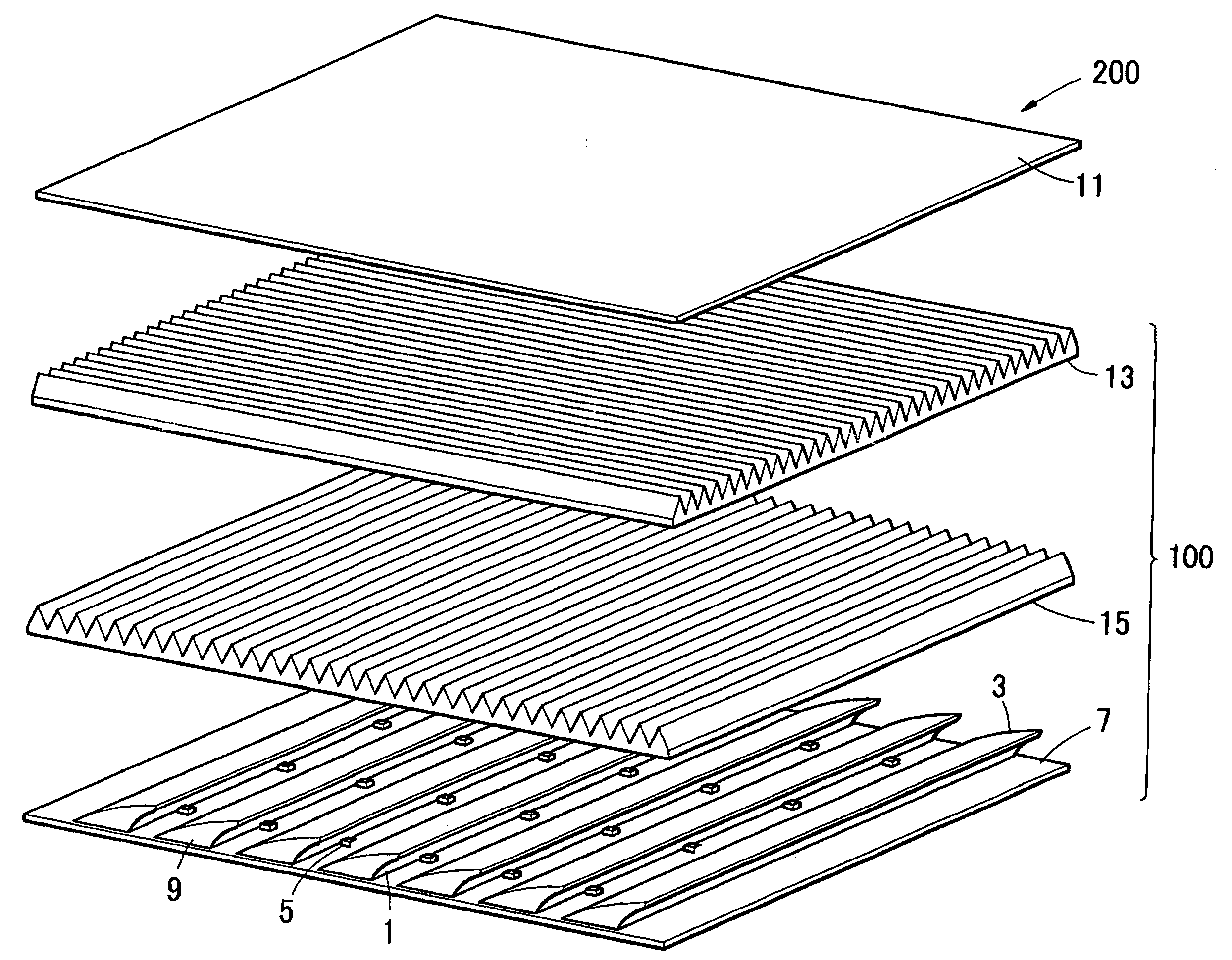
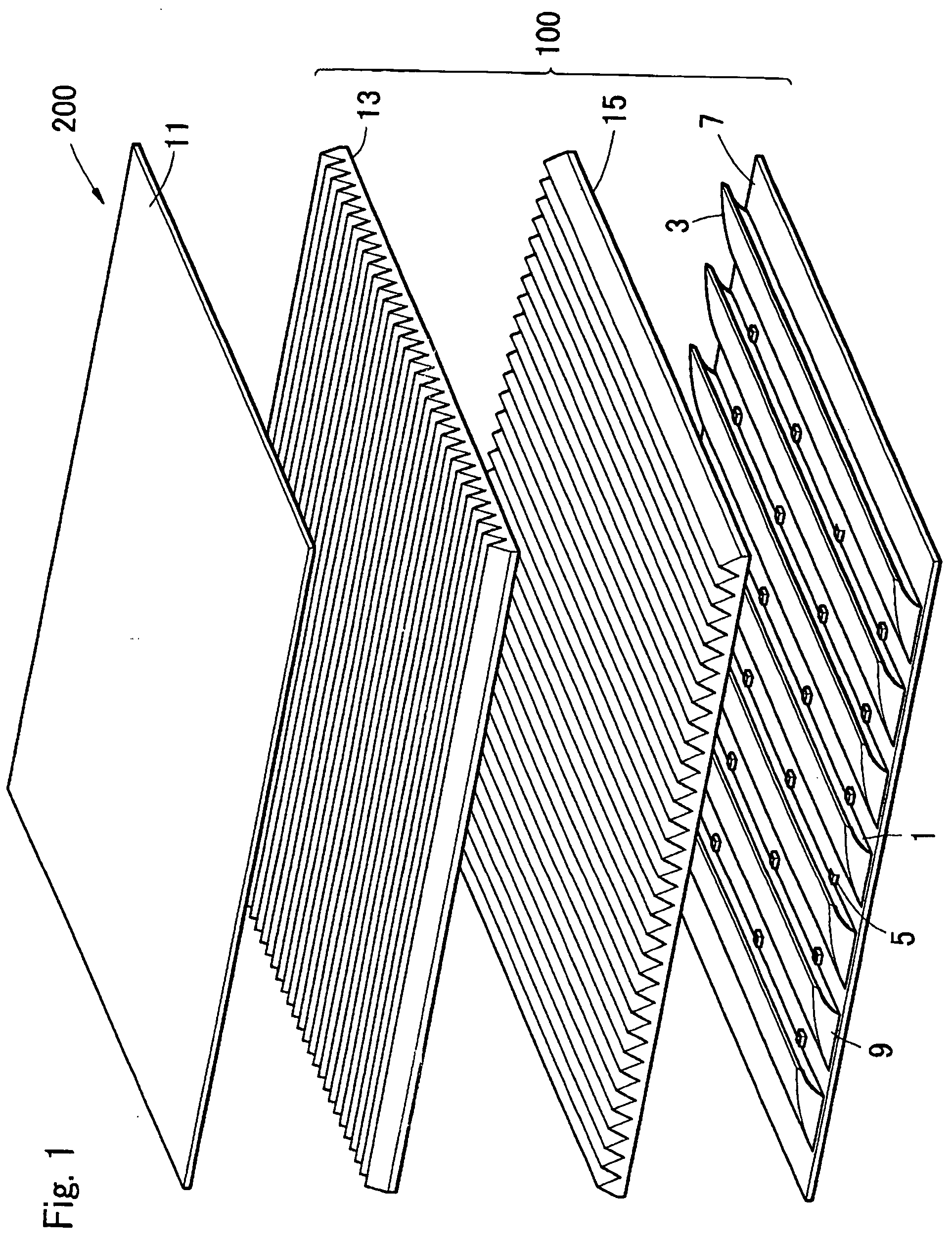
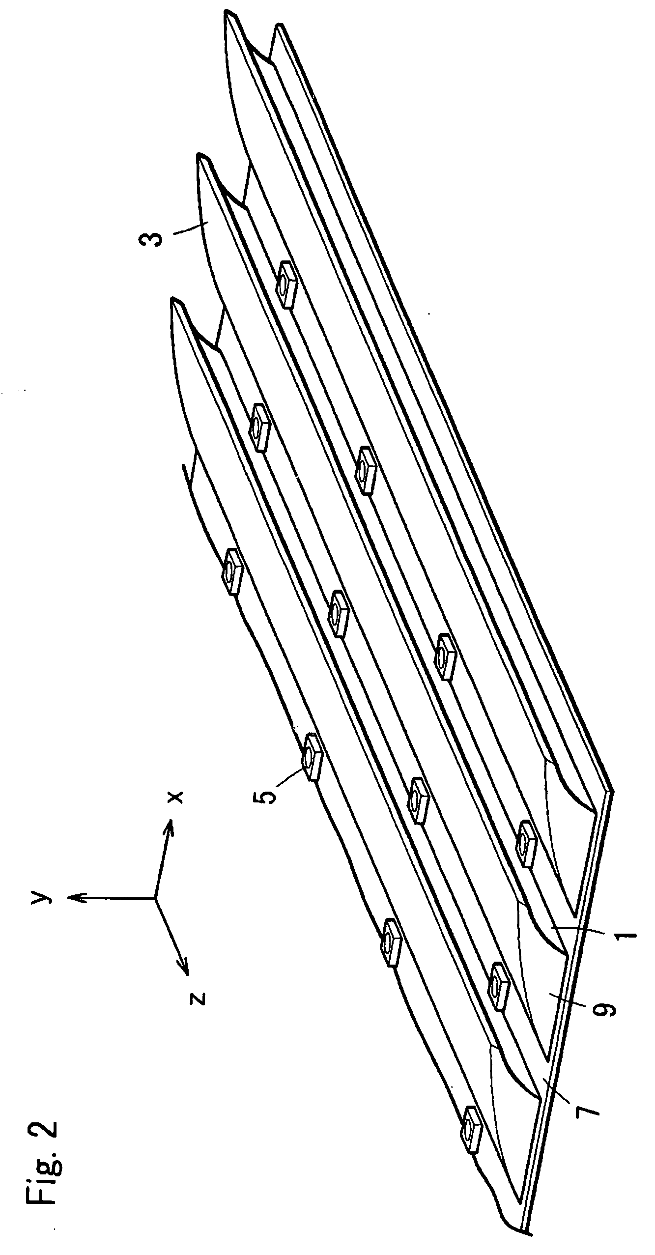
[0082] An aluminum-based substrate is used as the support substrate 7.

[0083] The reflector 9 is made of a white polycarbonate resin. The first surface 1 is processed for mirror finish, while the second surface 3 is processed with sand blast. The reflector is formed in hyperbolic cylinder surface in both the first surface 1 and the second surface 3 as shown in FIG. 4A. The light emitting diode used as the light source is located at the focal point of the first surface 1. The reflector measures 32 mm along the shorter side (x axis direction in FIG. 2) and 200 mm along the longer side (z axis direction in FIG. 2). Each of the reflectors is disposed to cover four light emitting diodes 5. 15 reflectors 9 are disposed in the direction of the shorter side, and 4 reflectors 9 are disposed in the direction of the longer side, in an array of 15 rows by 4 columns. Two prism sheets are disposed right above the ref...

example 2

[0085] Components of Example 2 of the present invention will be described below. Constitution is similar to that of Example 1 unless otherwise specified.

[0086] The reflector 9 is made of an acrylic resin. The first surface 1 is formed in parabolic cylinder surface and is coated with Ag by vapor deposition to form a mirror surface as shown in FIG. 3C. The second surface 3 is formed in a flat surface and is covered by a light diffusing sheet made of a white polycarbonate resin.

[0087] With this constitution and the rest similar to that of Example 1, the surface light emitting apparatus showed characteristics comparable to those of Example 1.

[0088] The surface light emitting apparatus of the present invention can be applied to the backlight source of the liquid crystal display apparatus used to display pictures in channel letter, computer, word processor, television receiver and the like, and also to other wide range of applications.


PUM


Abstract

A surface light emitting apparatus that can be made smaller in depth and lighter in weight and has high uniformity in luminance over the light emitting surface is disclosed. The surface light emitting apparatus of the present invention comprising a substrate, a plurality of light sources on the substrate, and a plurality of reflectors on the substrate, each of the reflectors having a first surface that covers the light sources and a second surface that reflects or scatters the irradiated light, wherein the reflectors are disposed so that the second surface is irradiated with a light emitted by the light source by the first surface of the adjacent reflector, and the light reflected or scattered by the second surface is emitted to outside.

Description

BACKGROUND OF THE INVENTION [0001] 1. Field of the Invention [0002] The present invention relates to a surface light emitting apparatus that uses a plurality of light sources, and, more particularly, to a surface light emitting apparatus having a relatively large area of light emitting surface. [0003] 2. Description of the Related Art [0004] Liquid crystal display apparatuses are commonly used in portable electronic devices and various image display apparatuses today. The liquid crystal display apparatus is constituted from liquid crystal cell, prism sheet, a diffusion sheet, a backlight and other major components. For the backlight source, LED, cold cathode tube or the like is used. Different types of backlight source have their own features and are selected according to the application. For example, a backlight source employing the cold cathode tube is used in a relatively large liquid crystal display apparatus, and a backlight source employing the LED is used in a small liquid cr...

Claims


Application Information

Patent Timeline
IPC IPC(8): H01K1/26H01K1/30H01J61/40H01J5/16
CPCG02F1/133603G02F1/133605G02F1/133611
Inventor NAKANO, KOJIINUZUKA, TOMOAKI
Owner NICHIA CORP
Why Eureka
Try Eureka