Method and apparatus for controlling privacy mask display

Inactive Publication Date: 2006-07-20
LG ELECTRONICS INC
View PDF2 Cites 21 Cited by
  • Summary
  • Abstract
  • Description
  • Claims
  • Application Information

AI Technical Summary

Benefits of technology

[0019] An object of the present invention is to pro

Problems solved by technology

However, if the monitoring direction of the monitoring camera 100 is changed through the panning operation as in the former case, it takes a relatively long time to rotate the pan motor by 180°.
However, in spite of the adjustment of the position and/or size of the privacy mask in response to the rotation or zooming of the monitoring camera 100, the adjusted privacy mask may inaccurately mask the monitored image that is shifted and/or enlarged/reduced.
In particular, when the monitoring camera 100 is zoomed in or out (change of a zoom ratio), inaccurate adjustment of the privacy mask may occur frequently.
In relation to the change o

Method used


Image

  • Method and apparatus for controlling privacy mask display
  • Method and apparatus for controlling privacy mask display
  • Method and apparatus for controlling privacy mask display

Examples


Example

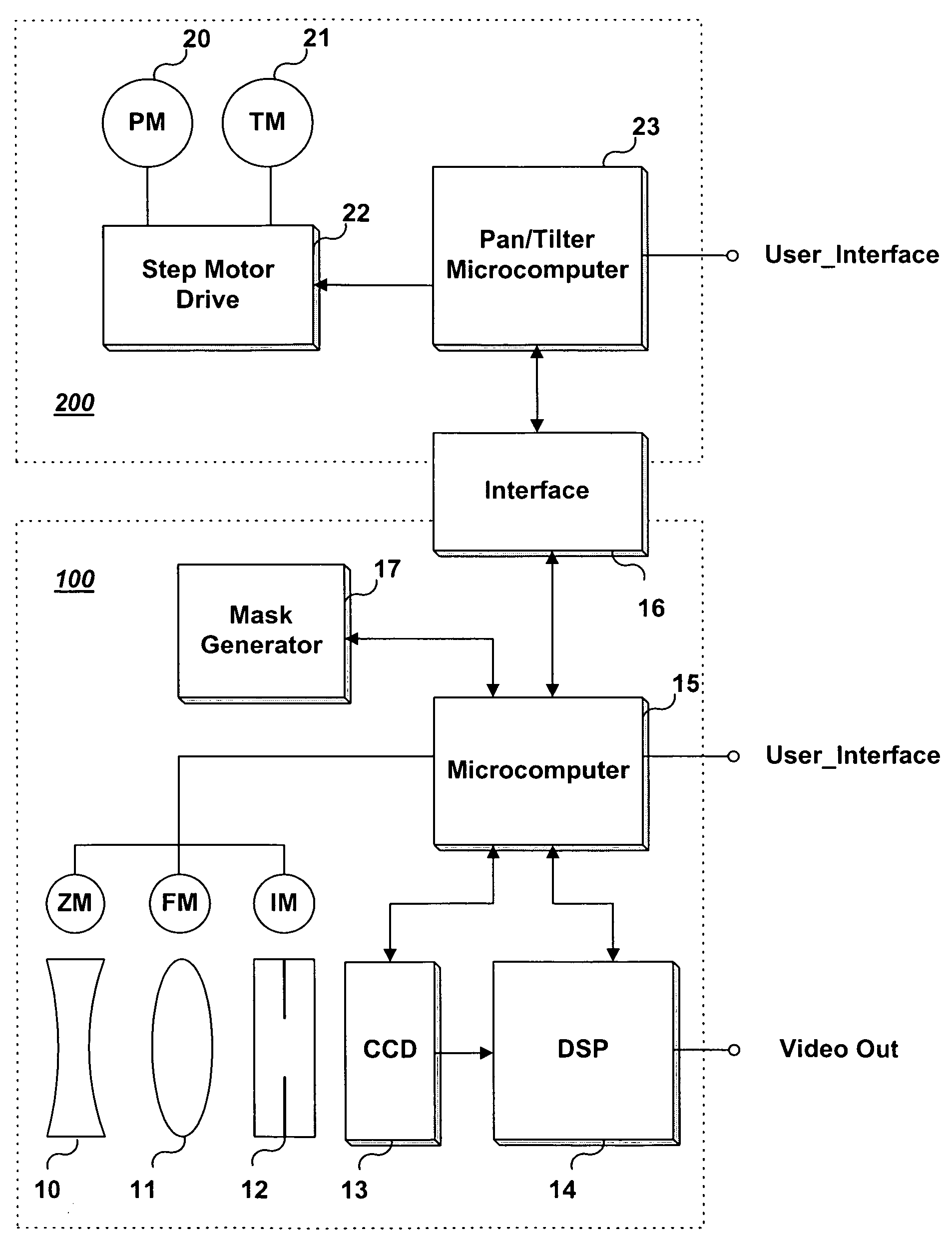
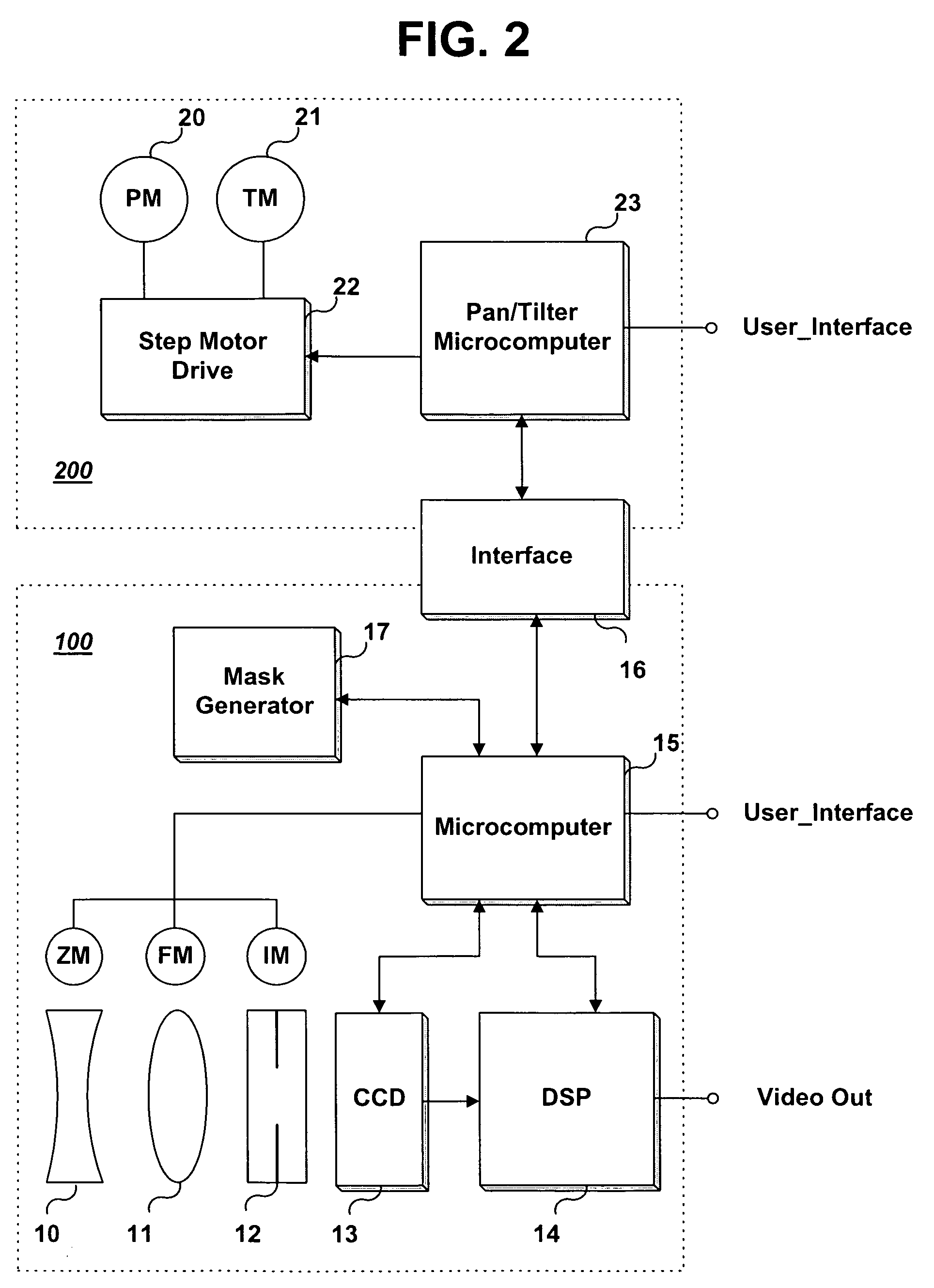
[0030]FIG. 2 shows the configurations of a monitoring camera and a pan / tilter. The monitoring camera 100 includes a zoom lens 10, a focus lens 11, an iris 12, a charge coupled device (CCD) 13, a digital signal processor 14, a microcomputer 15, an interface 16, and a mask generator 17. The pan / tilter 200 includes a pan motor 20, a tilt motor 21, a step motor drive 22, and a pan / tilter microcomputer 23.

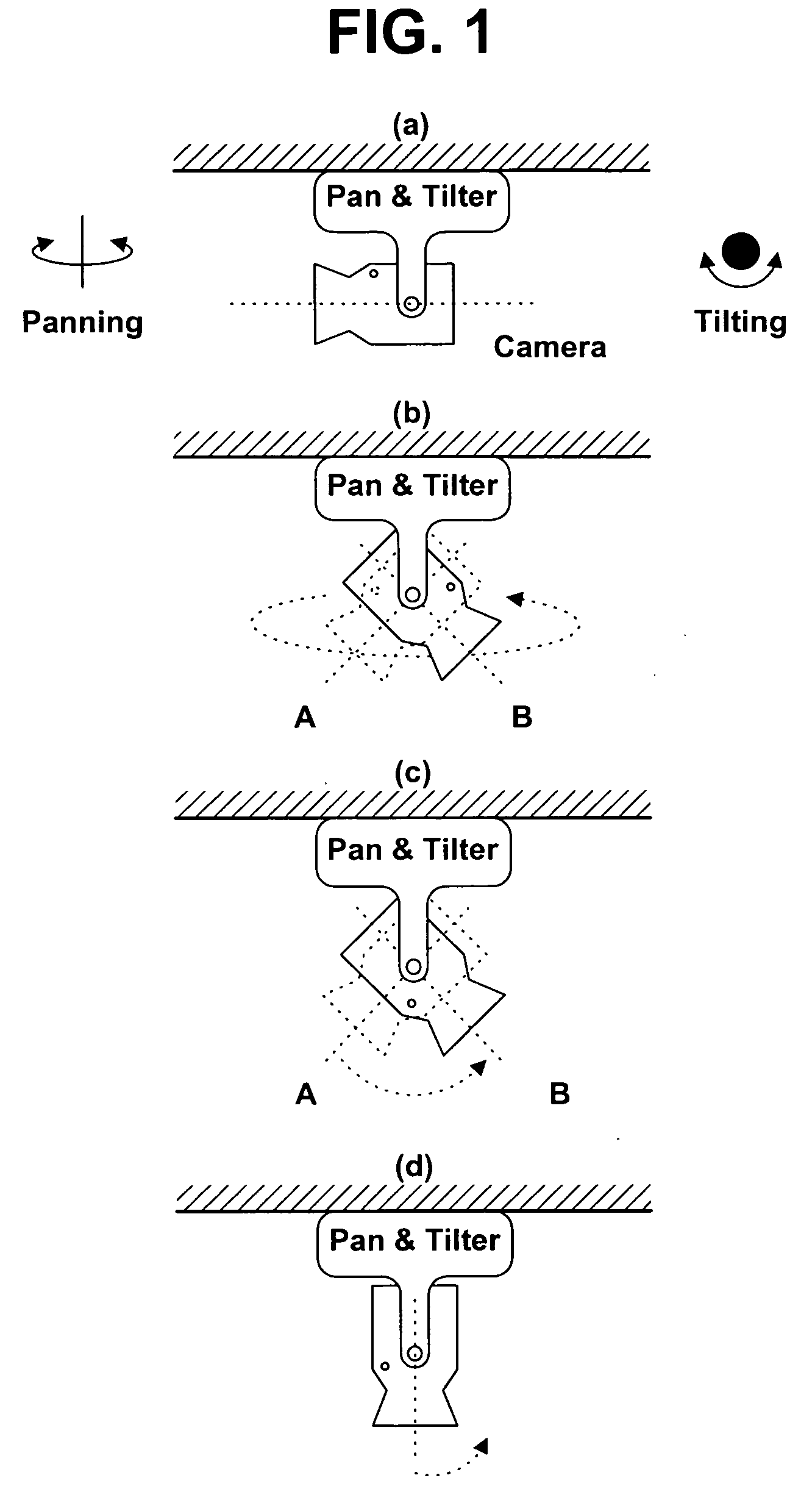
[0031] Each of the pan motor 20 and the tilt motor 21 is a step motor. To position the monitoring camera 100 such that it photographs a target object at an angle desired by the user, the pan / tilter microcomputer 23 controls the step motor drive 22 to rotate the pan motor 20 and tilt motor 21, and detects panning (horizontal) and tilting (vertical) rotation angles, or current pan and tilt angles.

[0032] Thus, the monitoring camera 100 can monitor all around a place where the monitoring camera 100 is installed by being shifted to observe various areas of the place of installation through...


PUM


Abstract

A method and an apparatus for controlling a privacy mask display includes a monitoring camera which is if tilted and its tilt angle becomes greater than 90° when a privacy mask to mask a specific target object in a captured image frame is displayed, an image and the privacy mask in the frame are rotated 180° with respect to the CCD center axis, and the optical center axis stored in the apparatus is also rotated 180° with respect to the CCD center axis. Afterwards, if the zoom ratio of the monitoring camera changes, the size and position of the privacy mask are adjusted relative to the optical center axis rotated 180° with respect to the CCD center axis. It is therefore possible to freely perform zooming and tilting operations without danger of exposing the privacy-protected target object even under the condition that the optical center axis and the CCD center axis of the monitoring camera do not coincide.

Description

[0001] This application claims priority to Korean Patent Application No. 10-2004-0106085 filed on Dec. 15, 2004 and Korean Patent Application No. 10-2005-0053022 filed on Jun. 20, 2005. The disclosures of the previous applications are incorporated by reference herein. BACKGROUND OF THE INVENTION [0002] 1. Field of the Invention [0003] The present invention relates to a method and apparatus for a camera, and more particularly to a method and an apparatus for controlling a privacy mask display. [0004] 2. Description of the Related Art [0005] A monitoring camera, a camera or video camera, may be installed to capture an image of a target object being monitored in a security-enforced area. The captured monitored image can be stored in a digital video recorder CDVR), which has been made commercially available in recent years. The monitored image captured by the monitoring camera may contain privacy-related data such as facial images of unspecified persons, thereby generating concerns abou...

Claims


Application Information

Patent Timeline
IPC IPC(8): H04N5/232
CPCH04N5/232H04N23/635H04N23/695
Inventor KANG, KYUN HOSEO, SUNG HA
Owner LG ELECTRONICS INC
Why Eureka
Try Eureka