
Use of polarization for differentiation of information

a technology of information and polarization, applied in the field of polarization, can solve the problems of difficult demultiplexing in the time domain using optical components, restricted possibilities for signalling different types of information, and difficulty in forming headers or labels, so as to achieve the effect of reducing complexity and cos

Active Publication Date: 2006-07-20
TRANSPACKET
View PDF12 Cites 65 Cited by
  • Summary
  • Abstract
  • Description
  • Claims
  • Application Information

AI Technical Summary

Benefits of technology

[0022] The present invention is trying to avoid the problems mentioned earlier which are linked to today's solutions, since it presents a method and a system for signalling within optical or combined optical / electrical network characterized in that one at a first transmission node executes polarization multiplexing of transmitted traffic, and that at one or more intermediate nodes is executing one or more of the following processing of the transmitted traffic:

Problems solved by technology

As optical signal processing is still immature there are very restricted possibilities for signalling different types of information such as address information.
In connection with optical package switching transfer of address information in the form of a header or a label is a problem for discussion.
Demultiplexing in the time domain is difficult using optical components.
1a) Address and payload are separated by the use of separate optical wavelengths; this gives however a bad utilization of the wavelengths.
However, this solution may lead to a deterioration of the payload signal.
1c) In the EU-sponsored project “STOLAS” it is suggested to use frequency modulation for modulation of package header separated from the payload; however this method may also give a deterioration of the signal quality within the payload.
This increases component count of complex and yet technologically immature components.
In a statistical multiplexed packet switched network, services like constant delay, and no packet loss, can not be guaranteed due to the very nature of statistical multiplexing.
This may preclude the use of strict real-time applications, where delay is critical, and packet loss should be at an absolute minimum, like e.g. for remotely controlled surgery.
However, the control plane operates on an ms to s timescale, and cannot be optimized to the bursty traffic patterns of OPS, where packet durations are typically in the ps range.
Therefore, not even D-WRONs can achieve the throughput efficiency and granularity of statistical multiplexing.

Method used


Image

  • Use of polarization for differentiation of information
  • Use of polarization for differentiation of information
  • Use of polarization for differentiation of information

Examples


Embodiment Construction

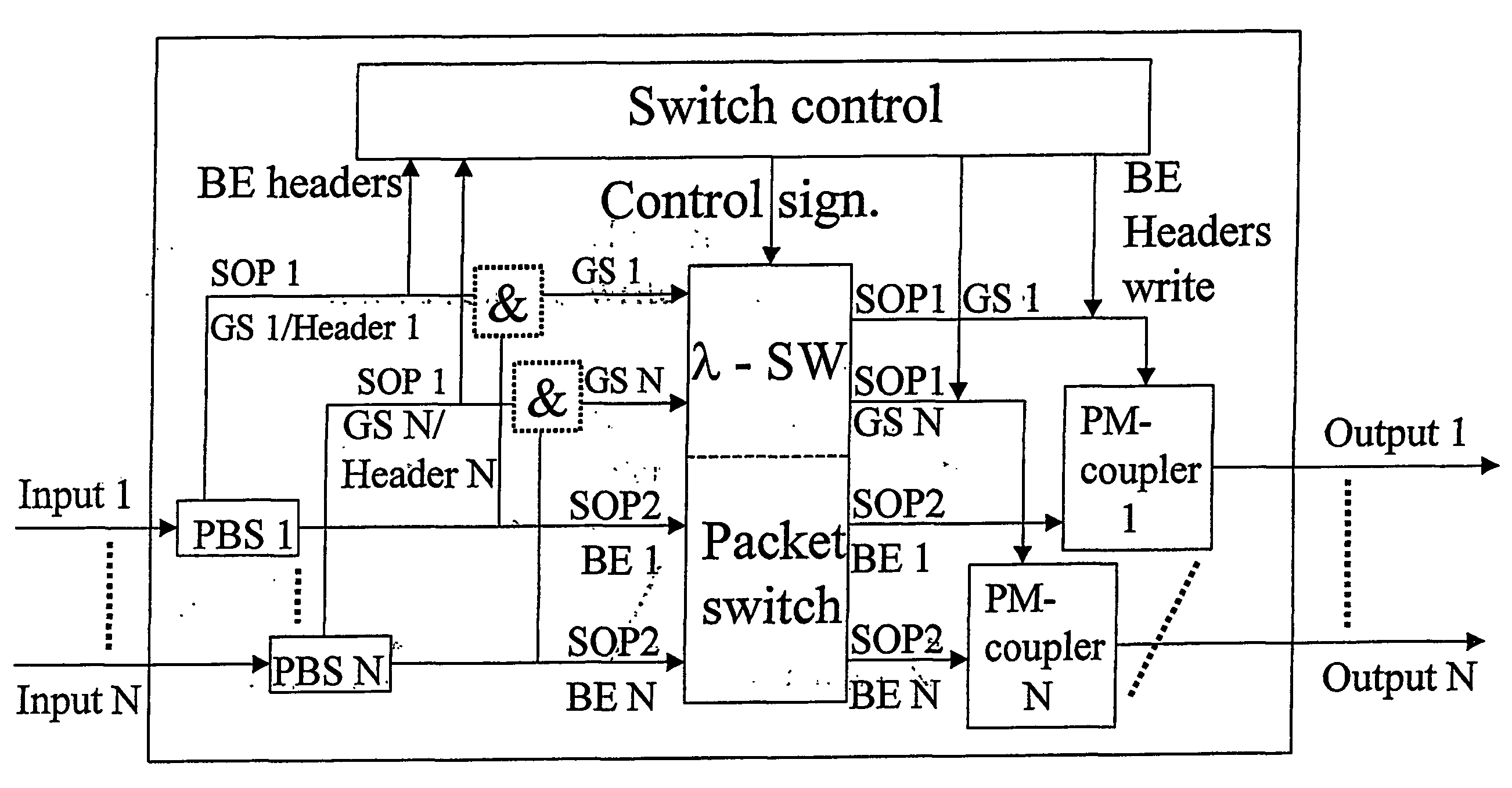
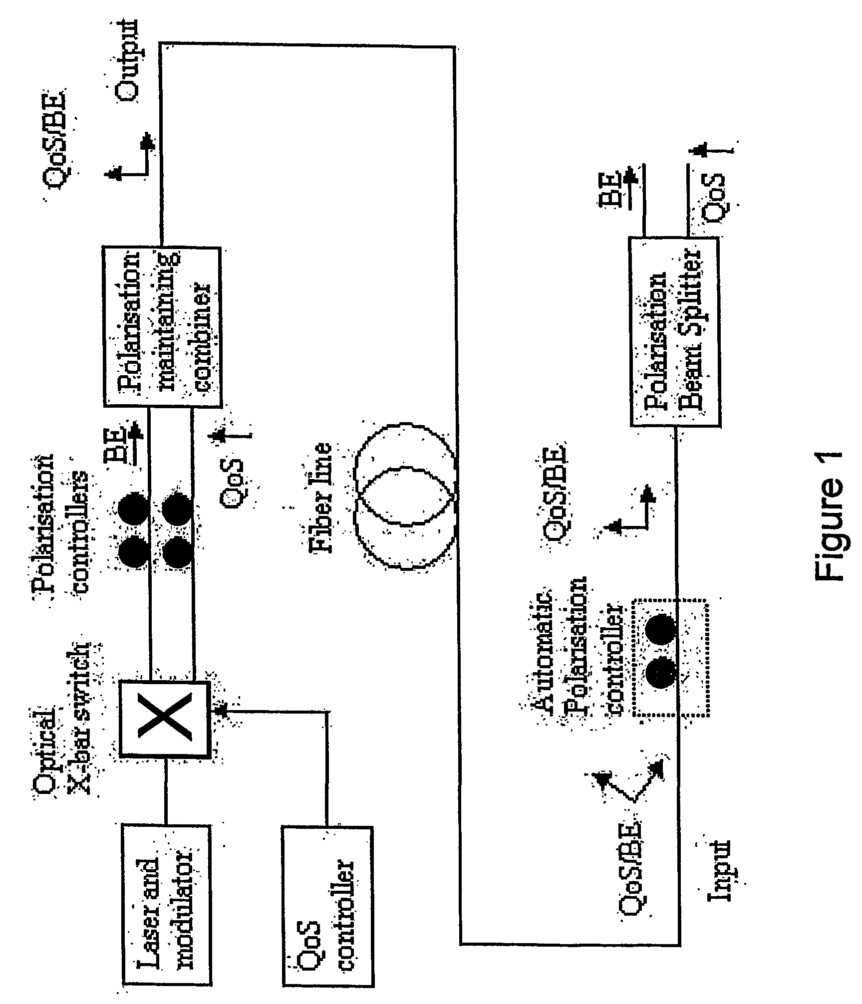
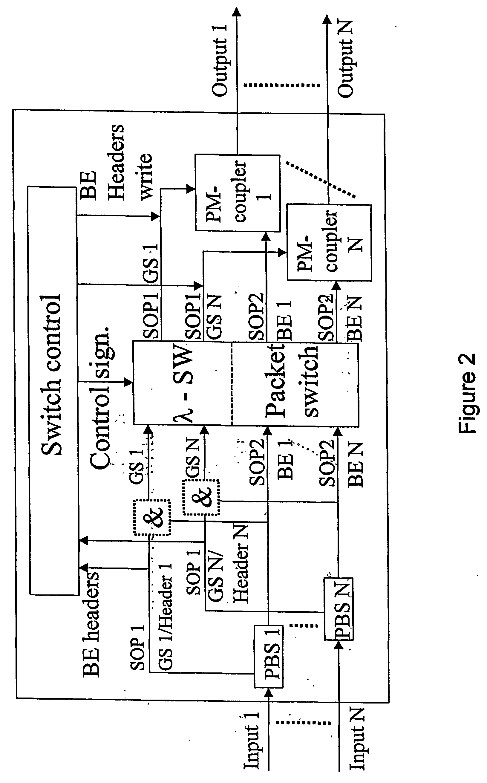
[0038] In the following it is given a detailed description of the present invention with support in the enclosed figures. As mentioned earlier there are several problems related to OPS. The present invention is redressing these problems by other things by using polarization for signalling. One can imagine the signalization being used in different ways:

[0039] 3a) Synchronizing, the state of polarization changes at the beginning of each package.

[0040] 3b) Header- and payload within each package is separated by orthogonal states of polarization.

[0041] 3c) QoS-classes are separated by assigning different priority to packages to be processed, thus having different polarization on the transmitter side.

[0042] In FIG. 1 it is given an example on how the states of polarization may be used for optical separation between two different QoS-classes. The same principle may be utilized to separate optically between a header- and a payload. The method may, with the use of a polarization beam sp...


PUM


Abstract

The present invention discloses a system for signalling within optical or combined optical / electronic networks wherein a first transmission node executes polarization multiplexing on transmitted traffic, and at one or more intermediate nodes one or more of the following processes are carried out on the sent traffic: demultiplexing by polarization and / or polarization and / or SOP-alignment. Further a method for packet handling within optical packet switched networks where, at a first transmission node carries out polarisation demultiplexing of transmitted traffic, and at one or a number of intermediate nodes carries out one or more of the following processes on the transmitted traffic; demultiplexing by polarisation, and / or polarisation and / or SOP-alignment. Said separation into states of polarisation is used in separation of QoS-classes.

Description

FIELD OF THE INVENTION [0001] The present invention relates to polarisation to distinguish QoS classes, and to distinguish payload and header in packages within communicational networks. More generally the present invention relates to a new and improved use of states of polarisation within all types of communicational networks. BACKGROUND OF THE INVENTION [0002] With the introduction and the development of optical networks it is a goal to reduce the cost and complecity of data transmission within Tele and data networks. A major factor for achieving this is to reduce the number of signal transformations between optical and electrical signals. Such a reduction will reduce the number of components within the networks elements and reduce the need for electronic signal processing. Further a reduction in the number of components within the networks element will result in a reduction of the sources of errors, and hence reduced need for service and maintenance and an increased operational t...

Claims


Application Information

Patent Timeline
Patent Type & Authority Applications(United States)
IPC IPC(8): H04J14/00H04JH04J14/02H04J14/06H04Q11/00
CPCH04J14/02H04Q2011/0007H04Q2011/0035H04J14/06H04Q11/00
Inventor BJORNSTAD, STEINAR
Owner TRANSPACKET
Learn More