Temperature sensing device

Inactive Publication Date: 2006-07-20
LIAO CHI HONG
View PDF8 Cites 25 Cited by
  • Summary
  • Abstract
  • Description
  • Claims
  • Application Information

AI Technical Summary

Benefits of technology

[0015] Moreover, as the temperature sensing device is designed to monitor the body temperature change of one or more subjects, accurate body temperature measurements can be obtained without consuming

Problems solved by technology

However, such temperature sensing devices often have to be held by one person to measure the body temperatures of a number of test subjects.
Therefore, the process of measuring the body temperature is very time-consuming and causes inconvenience as well as influences one's working efficiency.
However, as such portable temperature sensing device does not directly contact with the test subject, the temperature measurements might be easily affected by environmental temperature to therefore lead to inaccuracy in temperature measurement, just like what has commonly happened when using other non-contact type temperature sensing devices.
Furthermore, regardless of whether using the foregoing temperature sensing devices or the portable temperatur

Method used


Image

  • Temperature sensing device
  • Temperature sensing device
  • Temperature sensing device

Examples


first embodiment

The First Embodiment

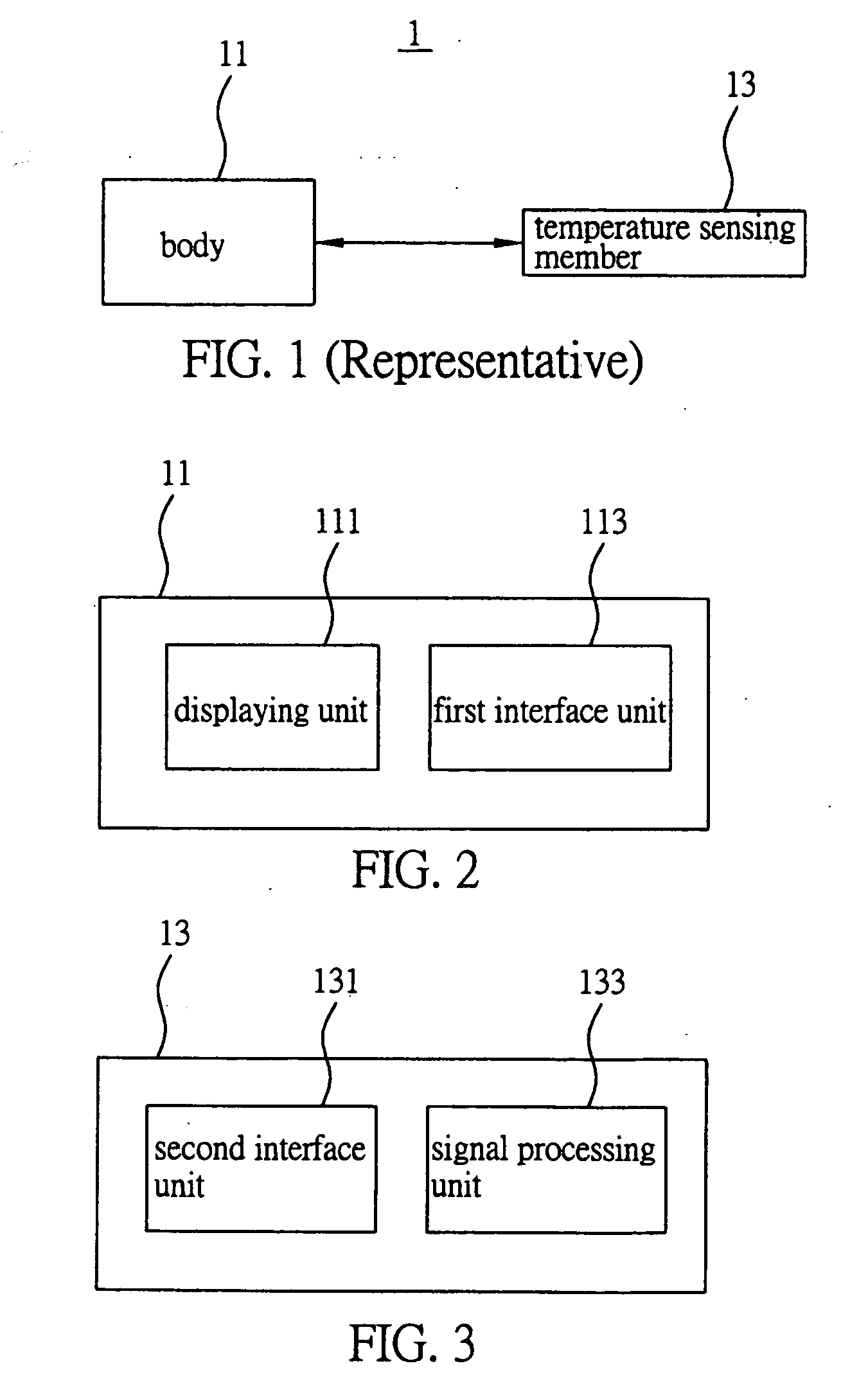
[0025]FIG. 1 to FIG. 3 are drawn according to the first embodiment of the present invention. A temperature sensing device 1 comprises a body 11 and a detachable temperature sensing member 13 freely provided in the body 11. The drawings are simplified diagrams and only elements relevant to the present invention are demonstrated. The actual shape and dimension ratios are not further described as they are not technical features of the present invention and can be modified depending on practical requirements.

[0026] Referring to FIG. 2, the body 11 comprises a displaying unit 111 and a first interface unit 113. The displaying unit 111 can be a screen for displaying the result of a body temperature measurement. The displayed result of body temperature measurement can be a value (such as 36° C. which can be an initial temperature parameter value and / or a temperature parameter value obtained after re-measurement, as subsequently described), a chart (such as a temperatur...

second embodiment

The Second Embodiment

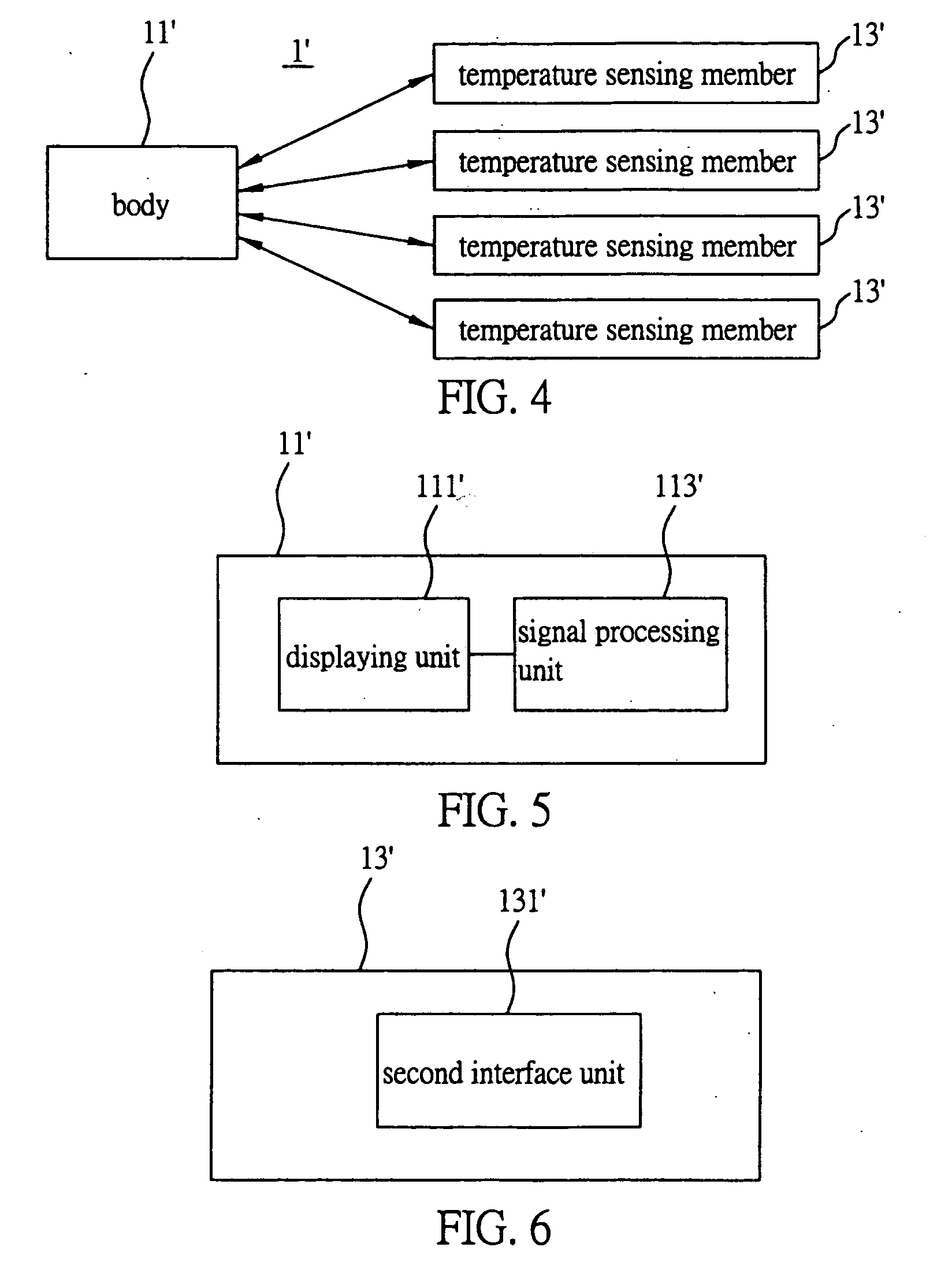
[0040]FIG. 4 to FIG. 6 are drawn according to the second embodiment of the present invention. A temperature sensing device 1′ comprises a body 11′ and a plurality of temperature sensing members 13′. The function of the temperature sensing device 1′ in the present embodiment is similar to that of the first embodiment. Therefore, only structures and functions different from the first embodiment are shown in describing the features and advantages for the present invention.

[0041] The present embodiment differs from the foregoing embodiment in that the temperature sensing device 1′ comprises a plurality of temperature sensing members 13′ which are respectively set on different test subjects, such that one body 11′ can be used to distantly and simultaneously measure and monitor body temperatures of these test subjects. Further, in order to minimize monitoring costs, a signal processing unit 113′ is provided in the body 11′ instead of in each of the temperature sensin...


PUM


Abstract

A temperature sensing device is proposed. The device includes a body and at least a temperature sensing member separated from the body by a predetermined distance. The body includes a displaying unit and a first interface unit, and the temperature sensing member is connected to the first interface unit of the body via a second interface unit. The temperature sensing member is set on a test subject using a detachable fixing unit and a measuring unit is used to measure the body temperature of the test subject. The measurement is received and processed by a signal processing unit, and subsequently transmitted to and displayed in the displaying unit. The signal processing unit can also be provided in the body or the temperature sensing member for converting and processing a temperature signal.

Description

FIELD OF THE INVENTION [0001] The present invention relates to a temperature sensing device, and more particularly, to a temperature sensing device which is able to detect body temperature changes when in contact with a test subject. BACKGROUND OF THE INVENTION [0002] Commonly marketed temperature sensing devices such as mercury thermometers, ear thermometers, electronic thermometers, infrared thermometers, and temperature measuring cards are employed to measure body temperature of a test subject using a contact or non-contact method, such that the devices can determine whether the body temperature of the test subject falls within a normal temperature range. [0003] In general, temperature sensing devices such as the foregoing mercury thermometer, ear thermometer, or electronic thermometer are usually used to measure the body temperature of the test subject when the test subject is sick or receives a health check-up or treatment in a clinic or hospital. In other words, except for a p...

Claims


Application Information

Patent Timeline
IPC IPC(8): A61B5/00
CPCA61B5/0008G01K1/022G01K1/024G01K1/026G01K13/002G01K13/20
Inventor LIAO, CHI-HONG
Owner LIAO CHI HONG
Why Eureka
Try Eureka