
Detection substrate, raman spectrum detection system, and raman spectrum detection method

a detection system and substrate technology, applied in the field of detection substrates, can solve the problems of affecting the contents of the to-be-detected object, increasing the cost of improving the substrate and complexity of the structure, and consuming a lot of production time and production costs, so as to facilitate simultaneous adsorption reactions and reduce the cost of time and manufacturing costs. , the effect of ultra-high resolution

Inactive Publication Date: 2021-12-23
TAMKANG UNIVERSITY
View PDF0 Cites 0 Cited by
  • Summary
  • Abstract
  • Description
  • Claims
  • Application Information

AI Technical Summary

Benefits of technology

The detection substrate in this patent has the advantage of being used with a Raman spectrum analyzer to measure molecules in a sample with high resolution. It can be made in large quantities and is not limited to specific molecules, reducing manufacturing costs. It can be used for various types of samples such as biomedical sensing objects, pesticides, bacteria, viruses, plastic particles, and has excellent detection effects.

Problems solved by technology

Therefore, a structure of a substrate needs to be constantly changed for different measurement systems, which consumes a lot of production time and production costs.
As a result, costs for improving the substrate and complexity of a structure are further increased.
If the detection substrate with the self-assembled monomolecular film is still used on a to-be-detected object other than glucose, an analysis result of contents in the to-be-detected object is affected, and a service life of the detection substrate is also significantly reduced.

Method used


Image

  • Detection substrate, raman spectrum detection system, and raman spectrum detection method
  • Detection substrate, raman spectrum detection system, and raman spectrum detection method
  • Detection substrate, raman spectrum detection system, and raman spectrum detection method

Examples


Embodiment Construction

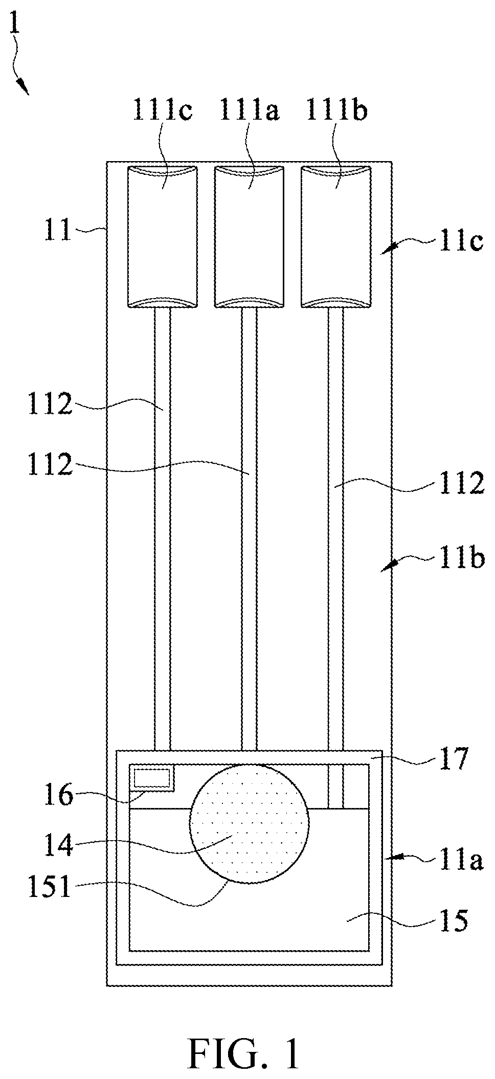
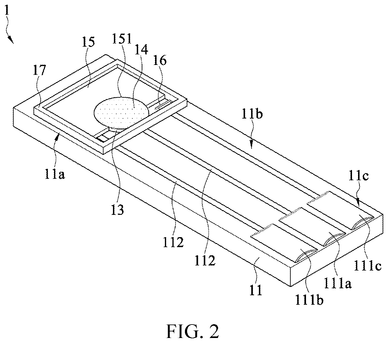
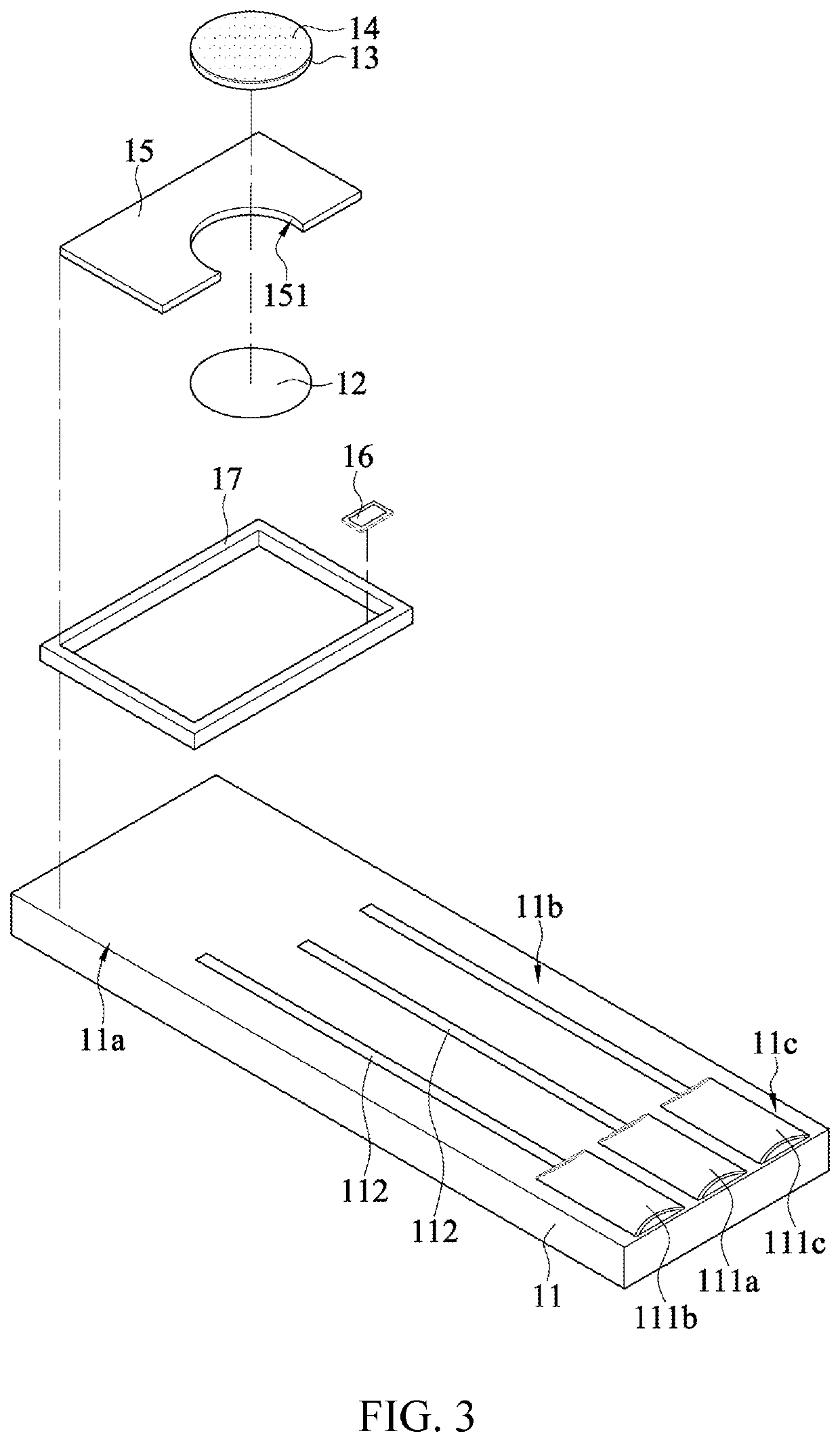
[0032]FIG. 1 to FIG. 3 are respectively a top view, a schematic diagram of an exterior, and an exploded view of a detection substrate 1 according to an embodiment of the present invention. The detection substrate 1 includes a substrate 11, a wetting layer 12, a barrier layer 13, a reaction layer 14, a counter electrode layer 15, and a reference electrode layer 16.

[0033]A measurement area 11a, a wiring area 11b, and an electrode area 11c are defined on the substrate 11. The substrate 11 includes a counter electrode (CE) 111b, a working electrode (WE) 111a, and a reference electrode (RE) 111c which are located on the electrode area 11c. In the embodiment shown in FIG. 1, the counter electrode 111b, the working electrode 111a, and the reference electrode 111c are integrated on the electrode area 11c. However, the present invention is not limited thereto. In some embodiments, there are a plurality of electrode areas 11c on the substrate 11, in which the counter electrode 111b, the worki...


PUM

PropertyMeasurementUnit
thicknessaaaaaaaaaa
thicknessaaaaaaaaaa
thicknessaaaaaaaaaa

Abstract

A detection substrate includes a substrate, a wetting layer, a barrier layer, a reaction layer, a counter electrode layer, a reference electrode layer, an insulating frame, and a plurality of wirings. The substrate includes a counter electrode, a working electrode, and a reference electrode. The reaction layer is located on the barrier layer. A surface of the reaction layer has a naturally micro-etched nano pattern. The counter electrode layer has an accommodating area which accommodates the reaction layer, and the naturally micro-etched nano pattern is exposed from the accommodating area. The insulating frame is located on a measurement area. The detection substrate has electrodes. During use, a predetermined reaction potential is applied to the detection substrate by an electrochemical device, and a Raman spectroscopy analysis is performed to obtain a strengthened Raman spectroscopy signal. A Raman spectrum detection system and a Raman spectrum detection method are also provided.

Description

CROSS-REFERENCE TO RELATED APPLICATION[0001]This non-provisional application claims priority under 35 U.S.C. § 119(a) to Patent Application No. 109121224 filed in Taiwan, R.O.C. on Jun. 22, 2020, the entire contents of which are hereby incorporated by reference.BACKGROUNDTechnical Field[0002]Disclosed is a detection substrate, especially a detection substrate that can be used in combination with an electrochemical device and a Raman spectrum analyzer. The present invention also provides a Raman spectrum detection system with the detection substrate and a Raman spectrum detection method.Related Art[0003]Each time the conventional surface-enhanced Raman spectroscopy (SERS) measurement technology is used for biological detection, necessary improvement is performed on a detection substrate to match a measurement system. Therefore, a structure of a substrate needs to be constantly changed for different measurement systems, which consumes a lot of production time and production costs.[000...

Claims


Application Information

Patent Timeline
Patent Type & Authority Applications(United States)
IPC IPC(8): G01N21/65G01N21/75G01J3/44
CPCG01N21/65G01J3/44G01N21/75G01N21/658G01N2021/1721G01N21/66G01J3/10
Inventor HSU, SHIH-CHIEHCHEN, CHING-HSIANGSUNG, CHENG-JUCHAO, SZU-HAN
Owner TAMKANG UNIVERSITY
Learn More