3D clampable valve flow reversing system

a technology of flow reversing and clamping valves, which is applied in the direction of valves, suction devices, medical devices, etc., can solve the problems of adding complexity to the setup

Inactive Publication Date: 2006-07-20
DSU MEDICAL
View PDF15 Cites 4 Cited by
  • Summary
  • Abstract
  • Description
  • Claims
  • Application Information

AI Technical Summary

Problems solved by technology

This can be readily done, but it

Method used


Image

  • 3D clampable valve flow reversing system
  • 3D clampable valve flow reversing system
  • 3D clampable valve flow reversing system

Examples


Embodiment Construction

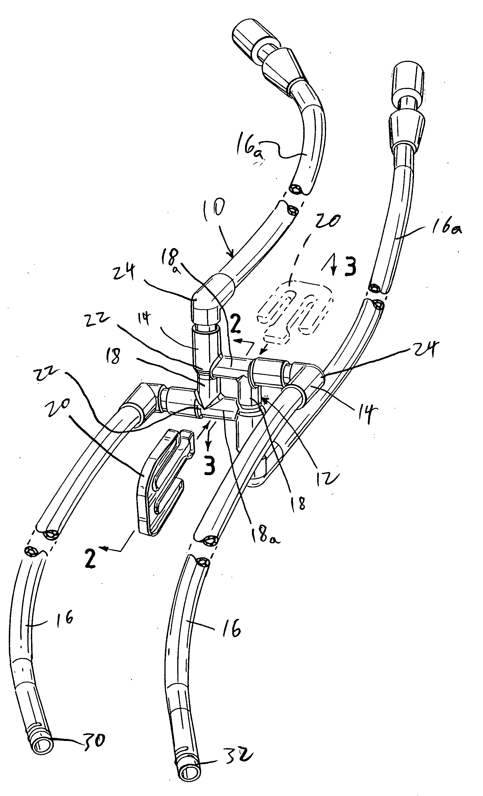
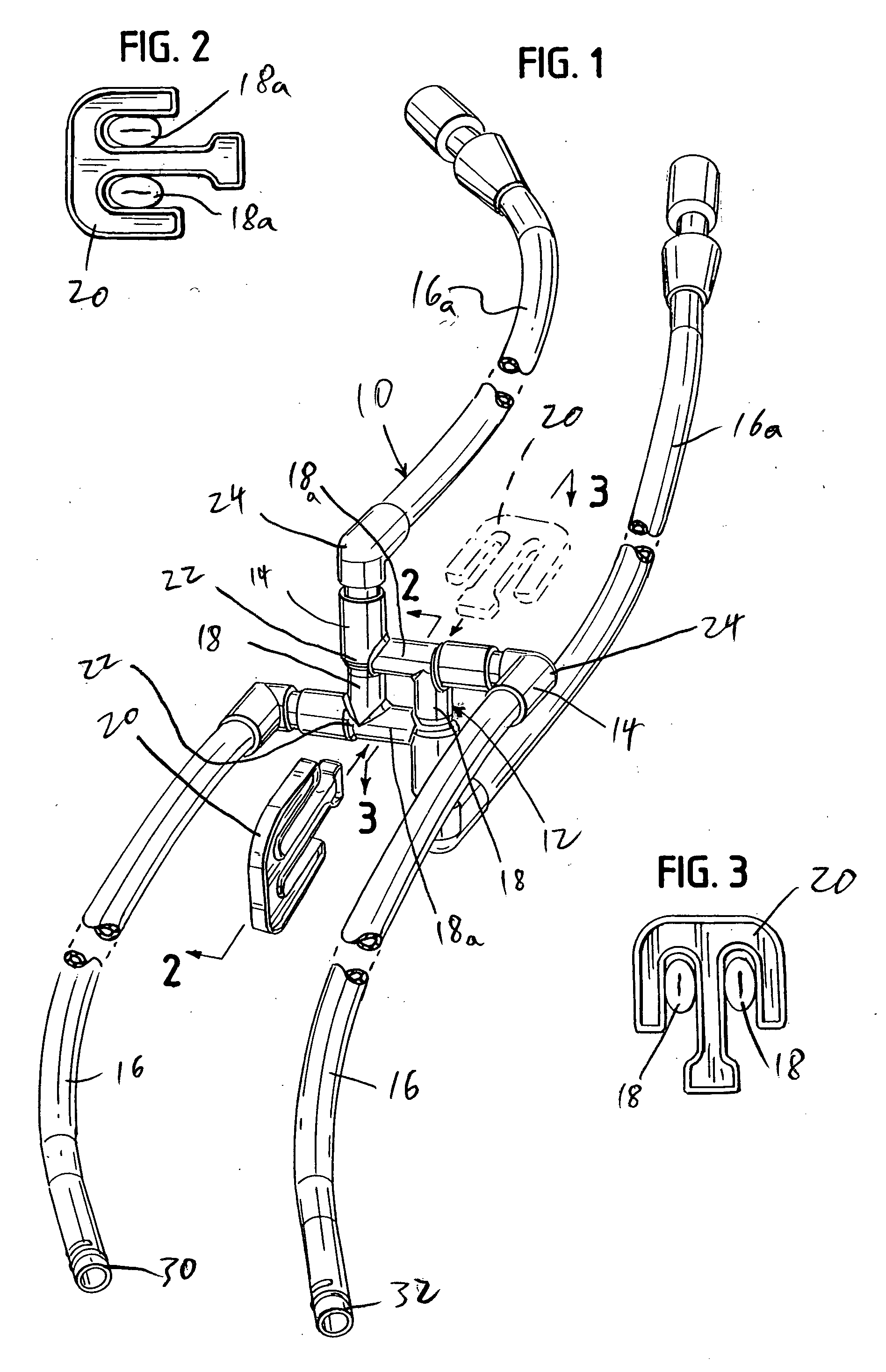
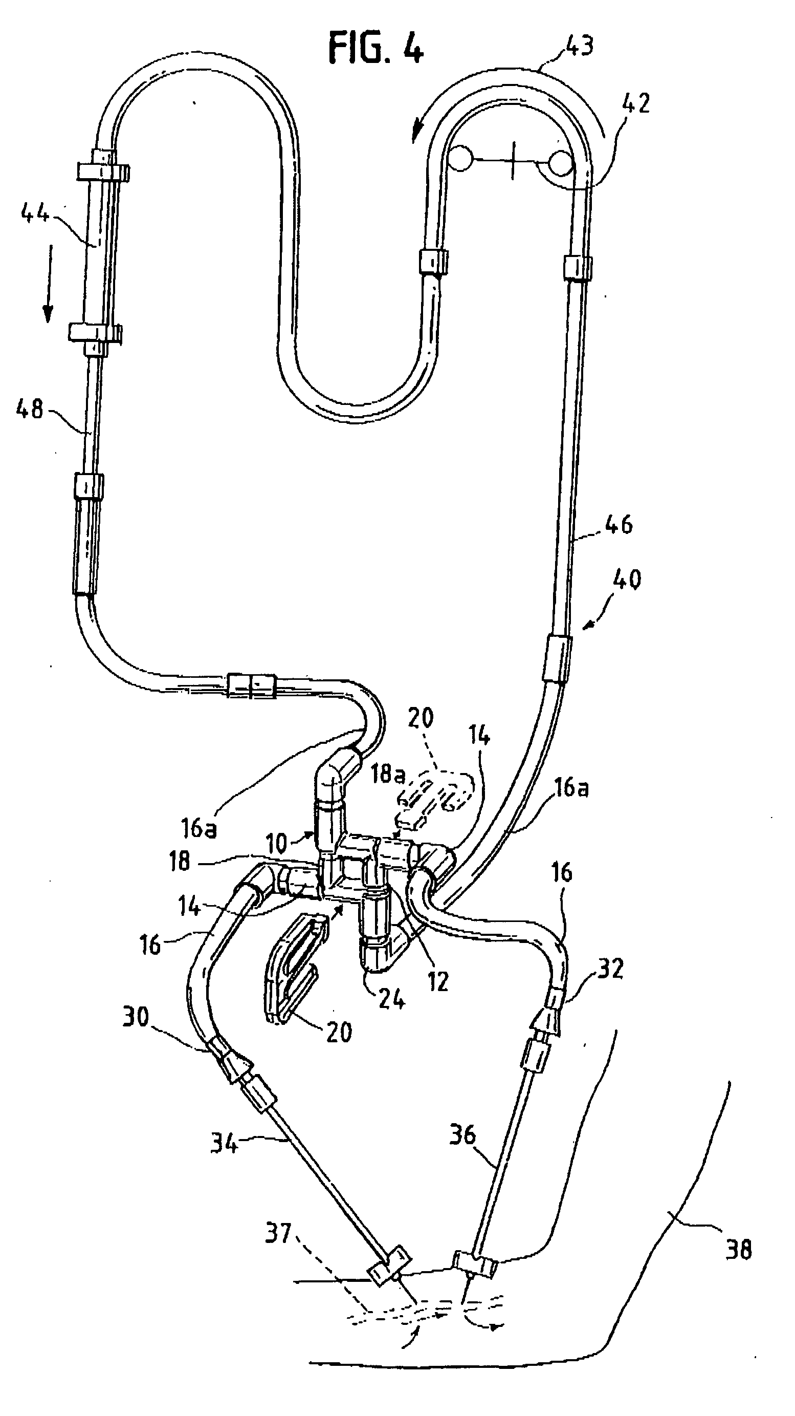
[0005] In accordance with one aspect of this invention, a flow reversal valve for a tubular fluid flow set comprises at least four tubular branches and a tubular loop, the tubular loop separately connecting with each of the tubular branches at ends thereof. Typically, the tubular loop substantially occupies a plane, and has clampable, collapsible tube sections between the branches (i.e., between the connection sites of the loop and the branches).

[0006] In some embodiments, each branch connects with the tubular loop in a direction which occupies a plane with the loop. However, in this case at least some, and typically all, of the tubular branches will also define a substantially rigid, angular bend directing the tubular branch out of the plane.

[0007] It is generally preferred for the tubular loop to be essentially quadrilateral in shape, and typically the tubular loop may be of essentially square shape. However, it would be possible to practice this invention with the tubular loop ...


PUM


Abstract

A flow reversal valve for a tubular fluid flow set comprises at least four tubular branches and a tubular loop. The tubular loop separately connects with each of the tubular branches at ends thereof, the tubular loop having collapsible, clampable tube sections between connections with the branches. At least some of the tubular branches connect at a transverse, third dimensional angle to the tubular loop, either directly, or through a substantially rigid, angular bend in the blood flow tubing adjacent to the tubular loop.

Description

BACKGROUND OF THE INVENTION [0001] In Bell et al. U.S. Pat. No. 6,695,807, a blood flow reversing system is disclosed for use in extracorporeal blood treatment, for circulating blood between a patient and an extracorporeal blood treatment device. The set portion has an arterial tube for conveying blood from the patient toward the blood treatment device, and a venous tube for conveying blood from the blood treatment device back towards the patient. A central, typically square, flow reversing section is provided, comprising portions of the arterial and venous tubes, and a pair of spaced, transverse tubes that each connect between the arterial tube and the venous tube. The arterial and venous tube portions and the spaced transverse first tubes are each capable of clamp sealing. [0002] Thus, a blood flow reversing set is provided in which the portions of the arterial and venous tube which are on the patient side of the flow reversing section can have the blood flow reversed, if desired,...

Claims


Application Information

Patent Timeline
IPC IPC(8): A61M37/00
CPCA61M1/3653A61M1/367A61M39/223A61M39/28A61M1/3658A61M1/3659
Inventor UTTERBERG, DAVID S.BELL, DAVID
Owner DSU MEDICAL
Why Eureka
Try Eureka