
Panel assembly for underdeck drainage and other applications

a technology for underdeck drainage and other applications, applied in the direction of snow traps, roof drainage, flooring, etc., can solve the problems of limiting and reducing the use of the space under the deck, so as to achieve the effect of prolonging the length

Inactive Publication Date: 2006-07-27
OMNIMAX INT INC
View PDF37 Cites 17 Cited by
  • Summary
  • Abstract
  • Description
  • Claims
  • Application Information

AI Technical Summary

Benefits of technology

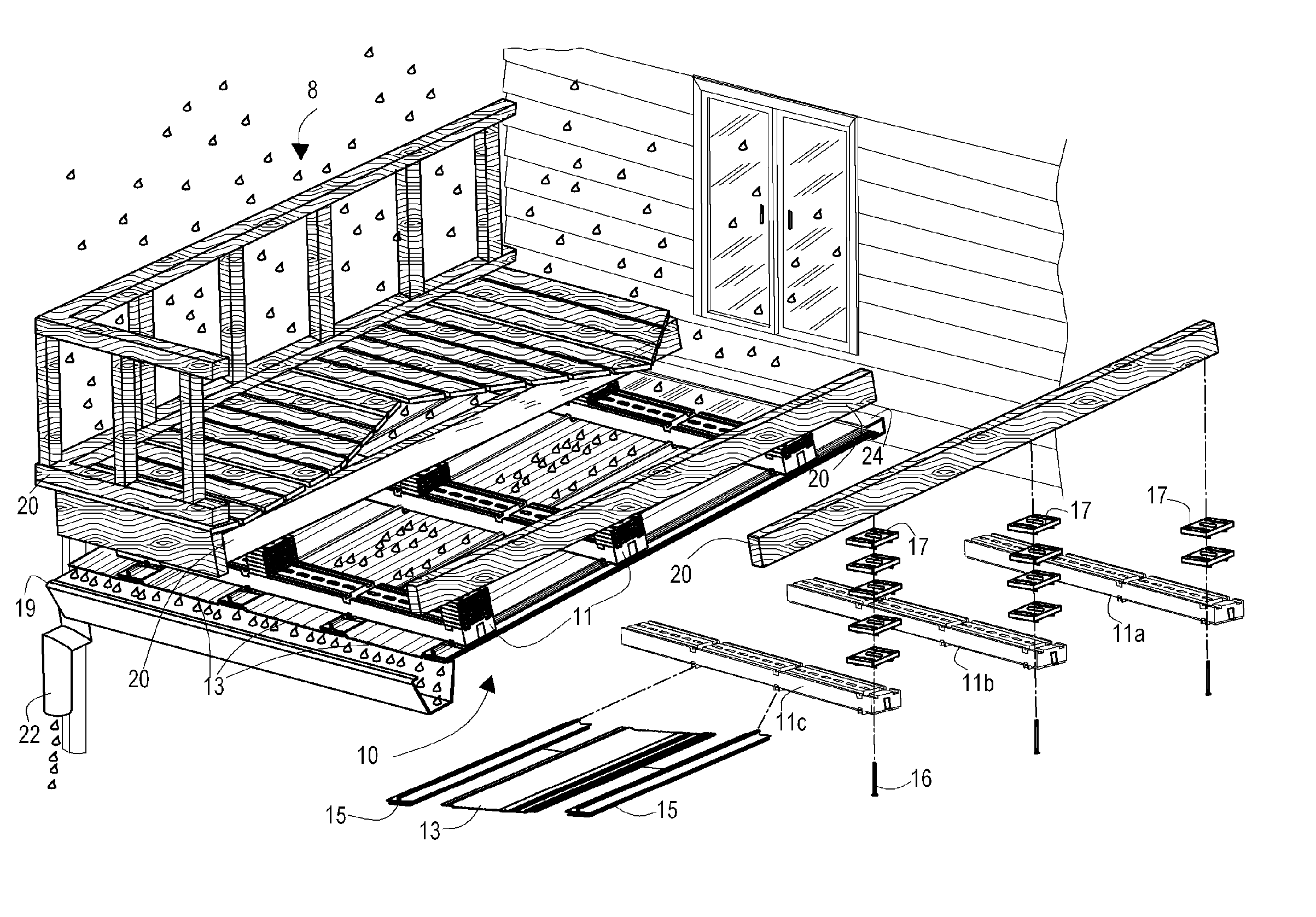
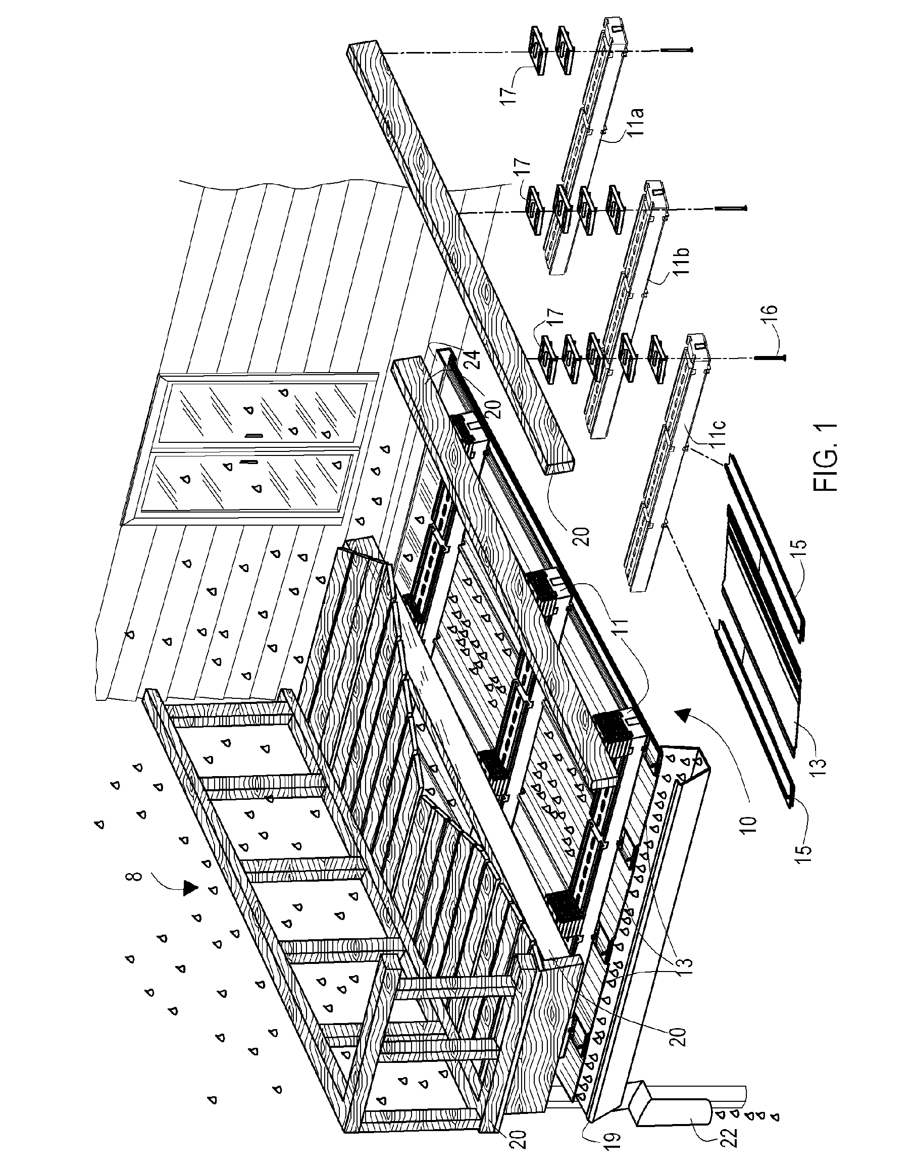
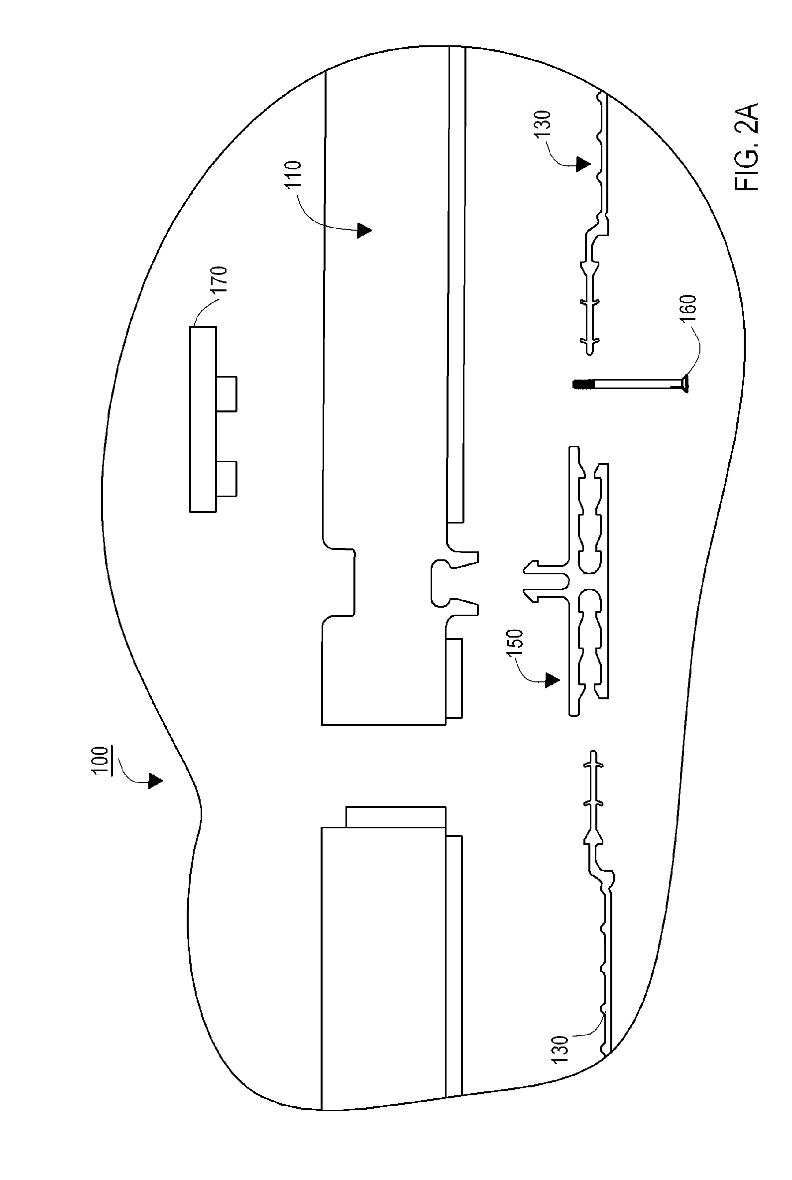
"The present invention is an underdeck drainage system for mounting beneath a deck assembly. The system includes a plurality of joist brackets, drainage panels, and joist bracket spacers. The joist brackets have a receptacle for receiving and supporting the drainage panels, and the drainage panels have ridges and flanges for engagement with the joist brackets. The joist bracket spacers have a frame with pegs and ribs for secure mounting. The system provides a more efficient and effective drainage system for decks, allowing water to be directed away from the deck's edge."

Problems solved by technology

This space may or may not be usable for other purposes, but often receives water that drains through spaces in the deck planking during rain events or cleaning.
However, the area under the deck, which may be used as a second patio or storage area, is exposed to the elements of nature, particularly rain that passes through the openings in the deck.
This severely limits the use of the space under the deck.
But many of the known systems have certain drawbacks and leave room for improvement.
Installation of this system requires extensive manual labor, with many multiple fasteners, and is thus expensive and time-consuming to install.
Although the structure is advertised as readily disgorging debris because of its flexible nature, its permanent mounting nature makes it difficult to readily remove, clean, and replace with the same panels.
One issue with this system is the diversion of water towards the joist gutters.
If the water flow is heavy, it can seep over the edges of the joist gutter mounting structure and contact with the wood of the joist.
Over time, this may result in damage to the bottom edges of the joists.
Furthermore, this design results in visible joist gutters and does not permit a flat, flush appearance of ceiling and water drainage system.
Further still, special collector panels are required for this system if a deck has inconsistent joist spacing, the joist rails are difficult to install at the edges, the panels easily dent and crease, and deck railing post fasteners and support braces can interfere with installation.
The material of the F-brackets is relatively thin and weak, and may not support a significant water load on the panels.
This can result in damage to the joists over time.
Furthermore, this system requires a 4 inch to 7 inch space between the bottom of the deck and the panels, which can diminish the amount of overhead room in certain applications.
Such systems are clearly inconvenient for preconstructed decks, as the decking must be removed in order to install the drainage system.
Significant sealing and caulking may be required along the extensive seams in this approach to prevent leakage, which is time-consuming and difficult to create a smooth appearance.
With many of these known underdeck drainage systems, over a period of time, the drainage panel may be degraded and / or damaged, and there may be leaves and / or other debris accumulated on the drainage panel surface so that the panel surfaces become clogged.
However, it is difficult or a least inconvenient to remove, clean, and / or replace components in many of these known drainage systems.

Method used


Image

  • Panel assembly for underdeck drainage and other applications
  • Panel assembly for underdeck drainage and other applications
  • Panel assembly for underdeck drainage and other applications

Examples


Embodiment Construction

[0051] The present invention is more particularly described in the following examples that are intended to be illustrative only since numerous modifications and variations therein will be apparent to those skilled in the art. Various embodiments of the invention are now described in detail. Refer now to the drawings, where like numbers indicate like parts throughout the views. As used in the description herein and throughout the claims that follow, the meaning of “a,”“an,” and “the” includes the plural reference unless the context clearly dictates otherwise. Also, as used in the description herein and throughout the claims that follow, the meaning of “in” includes “in” and “on” unless the context clearly dictates otherwise.

[0052] The description will be made as to the embodiments of the present invention in conjunction with the accompanying drawings FIGS. 1-15. In accordance with the purposes of this invention, as embodied and broadly described herein, this invention, in one aspect...


PUM

PropertyMeasurementUnit
lengthaaaaaaaaaa
surface areaaaaaaaaaaa
areaaaaaaaaaaa

Abstract

A panel assembly for providing underdeck water drainage and for other applications such as wall panels and skirting for exposed areas under building. The panel assembly, for an underdeck water drainage system, includes a plurality of joist brackets that are mounted transversely to and under the joists of a deck, a plurality of drainage panels, a plurality of drainage panel brackets, and a plurality of joist bracket spacers. The drainage panels may be slidingly engaged or snapped into separate panel brackets or into panel bracket portions of adjacent drainage panels. When properly installed, the underdeck drainage system will protect an area of interest, such as a patio or storage area under a deck, from rain water and keep the area dry. Another application of the present invention is to provide a shield, skirt, or cover for an exposed area under a deck, a home, a mobile home, a wall, or other place of interest.

Description

CROSS-REFERENCE TO RELATED PATENT APPLICATIONS [0001] This application claims priority to and the benefit of, pursuant to 35 U.S.C. §119(e), U.S. provisional patent application No. 60 / 643,232, filed Jan. 11, 2005, entitled “Underdeck Drainage II,” by Jeffrey E. Smith, and U.S. provisional patent application No. 60 / 595,558, filed Jul. 14, 2005, entitled “Underdeck Drainage System,” by Jeffrey E. Smith, which are incorporated herein by reference in their entirety.FIELD OF THE INVENTION [0002] The present invention generally relates to water drainage for decks on residential houses and other buildings, and more particularly, to a panel assembly for use in providing an underdeck water drainage system and for other applications such as wall panels, ceiling panels, and decorative exterior panels such as trailer and mobile home skirts and the like. BACKGROUND OF THE INVENTION [0003] Decks made of parallel planking are often constructed at residential houses and other buildings to provide a...

Claims


Application Information

Patent Timeline
Patent Type & Authority Applications(United States)
IPC IPC(8): E04D13/14
CPCE04B1/34342E04D11/005E04D13/0477E04F15/10E04F17/00
Inventor SMITH, JEFFREY E.
Owner OMNIMAX INT INC
Learn More