Operating pedal system of automobile

a technology of operating pedal and automobile, which is applied in the direction of pedestrian/occupant safety arrangement, mechanical control devices, instruments, etc., can solve the problems of deteriorating operation feeling of the operating pedal, and achieve the effect of excellent operation feeling

Inactive Publication Date: 2006-07-27
F TECH INC
View PDF5 Cites 52 Cited by
  • Summary
  • Abstract
  • Description
  • Claims
  • Application Information

AI Technical Summary

Benefits of technology

[0007] The present invention has been achieved in view of the above circumstances, and has an object to provide an operating pedal system of an automobile in which a support hole of a pivot of an operating pedal is formed into a circular shape conforming to an outer peripheral face

Problems solved by technology

Therefore, they have a disadvantage that the support hole has an imperfectly circular shape, and thus rattling is likely to occur on the release h

Method used


Image

  • Operating pedal system of automobile
  • Operating pedal system of automobile
  • Operating pedal system of automobile

Examples


first embodiment

[0026] the present invention shown in FIGS. 1 to 7 will be described.

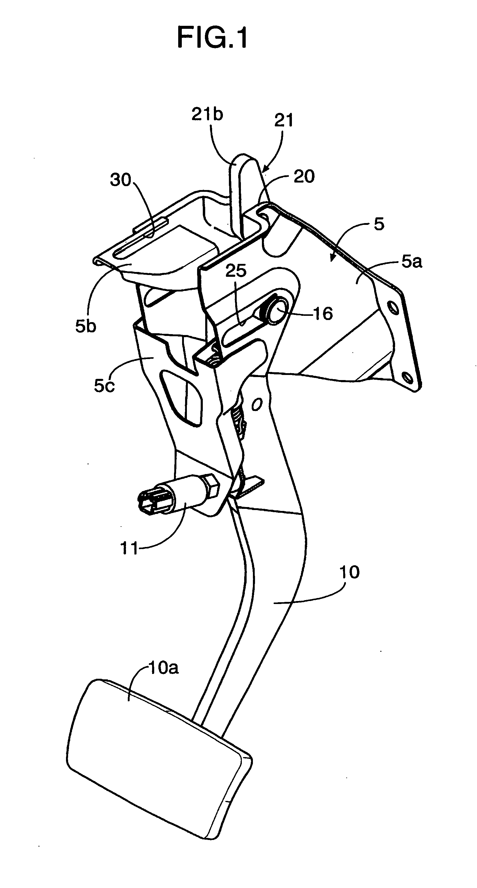
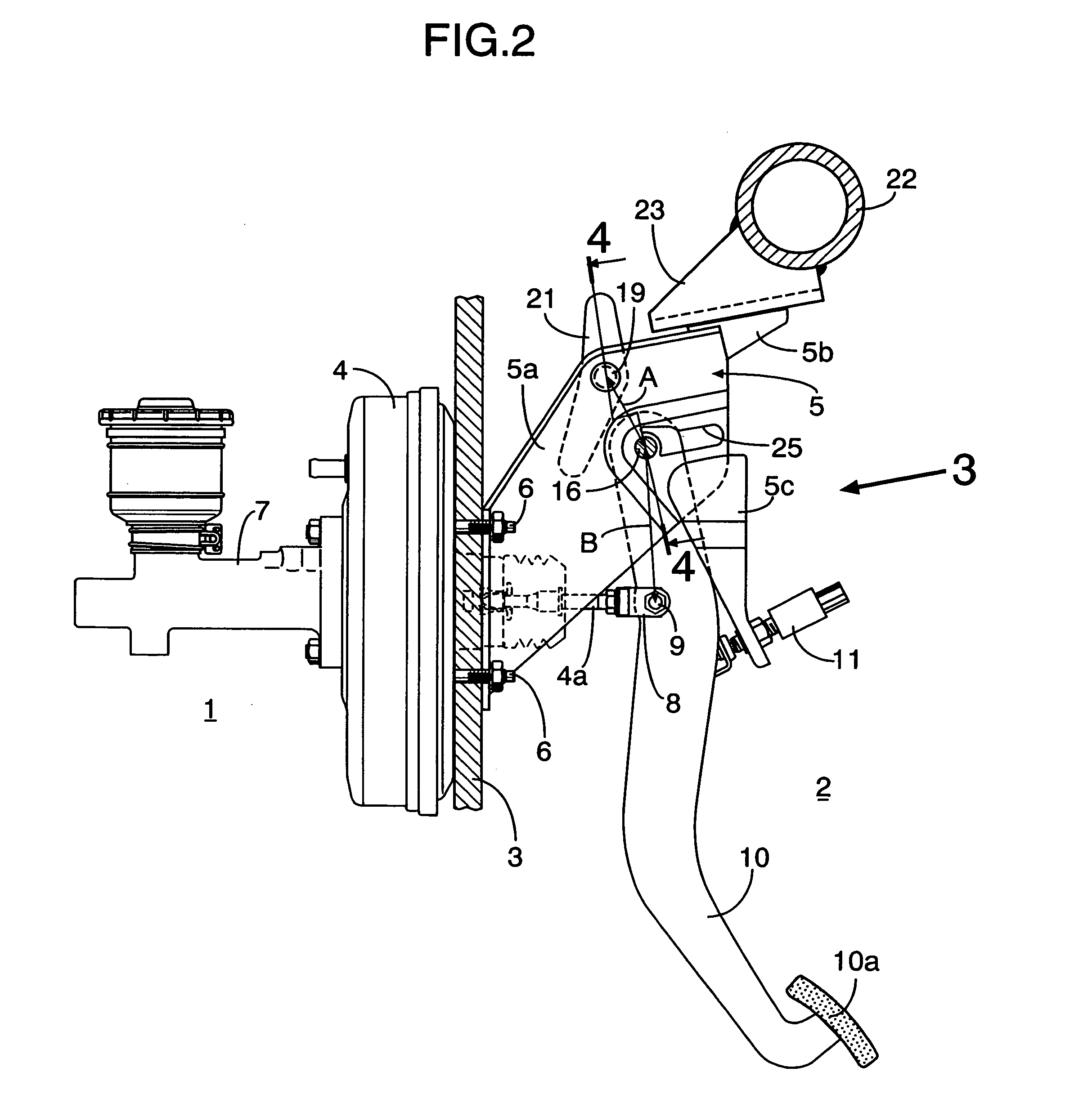
[0027] In FIGS. 1 to 3, firmly fixed by a plurality of bolts 6 to a dashboard 3 of a vehicle body separating an engine room 1 in a front part and a vehicle compartment 2 in a rear part in an automobile, are a negative pressure booster 4 placed in the engine room 1 and a bracket 5 placed in the vehicle compartment 2. Mounted on a front face of the negative pressure booster 4 is a brake master cylinder 7 boosted by the negative pressure booster 4. Connected to an output port of the brake master cylinder 7 is a hydraulic conduit pipe (not shown) coupled to wheel cylinders of a front wheel brake and a rear wheel brake.

[0028] The bracket 5 comprises: a pair of left and right sidewall plates 5a, 5a with their front ends fixed to the dashboard 3 by the bolts 6, 6; a ceiling plate 5b integrally connecting together upper ends of the sidewall plates 5a, 5a; and a rear wall plate 5c integrally connecting together rear ends o...

second embodiment

[0040] the present invention shown in FIGS. 8 to 10 will now be described.

[0041] A bell-crank shaped relay lever 32 is coupled via the coupling shaft 9 to the input lever 4a and supported by the pivot 16. The lower arm 21a of the control lever 21 is placed to face a front face of the relay lever 32 near the pivot 16.

[0042] The brake pedal 10 is supported via another pivot 33 by the bracket 5 below the relay lever 32, and coupled via a link 34 to the relay lever 32. The other components are substantially same as those of the first embodiment, and thus the same reference numerals and symbols are given to components in FIGS. 8 to 10 corresponding to those of the first embodiment, and redundant explanations are omitted.

[0043] According to the second embodiment, the speed of movement of the brake pedal 10 can be increased or decreased and transmitted to the input lever 4a by arbitrarily setting a lever ratio between the brake pedal 10 and the relay lever 32 as well as an input-side lev...


PUM


Abstract

A long hole is provided on a bracket fixedly provided on a rear face of a dashboard such that the long hole is adjacent to a support hole supporting a pivot of an operating pedal with a partition wall provided between the long hole and the long hole. Also, a control lever is pivotally supported on a front face of the pivot via the operating pedal such that a lower arm of the control lever faces the front face. A stopper member fixedly provided on a vehicle body faces an upper arm of the control lever from behind. Therefore, when the control lever abuts against the stopper member and rotates as the dashboard is deformed rearward, the pivot breaks the partition wall to move rearward within the long hole due to an excessive load received from the control lever. Thus, the support hole of the pivot of the operating pedal can be formed into a circular shape conforming to an outer peripheral face of the pivot, so that no rattling occurs between the support hole and the pivot. Further, when the dashboard is deformed rearward, the pivot is moved rearward to prevent a tread portion of the operating pedal from coming closer to a driver.

Description

RELATED APPLICATION DATA [0001] The present invention is based upon Japanese priority application No. 2004-356978, which is hereby incorporated in its entirety herein by reference. BACKGROUND OF THE INVENTION [0002] 1. Field of the Invention [0003] The present invention relates to an operating pedal system of an automobile in which an operating pedal for operating an operation device mounted on a front face of a dashboard of a vehicle body or a relay lever associated with the operating pedal is mounted on a bracket fixedly provided on a rear face of the dashboard via a pivot, and particularly to an improvement of an operating pedal system in which, even when a dashboard supporting the bracket is deformed rearward upon head-on collision of the vehicle, the pivot is moved rearward to prevent a tread portion of the operating pedal from coming closer to a driver. [0004] 2. Description of the Related Art [0005] Japanese Patent Application Laid-open Nos. 11-139346 and 2001-47986 disclose ...

Claims


Application Information

Patent Timeline
IPC IPC(8): G05G1/14B60R21/02B60T7/06B62D25/08G05G1/30G05G1/327
CPCB60T7/065Y10T74/20528G05G1/327B60T7/06
Inventor SATO, JUN
Owner F TECH INC
Why Eureka
Try Eureka