

Take up-type screen device whose lock is releasable from either inside or outside
- Summary
- Abstract
- Description
- Claims
- Application Information
AI Technical Summary
Benefits of technology
Problems solved by technology
Method used
Image


Examples
first embodiment
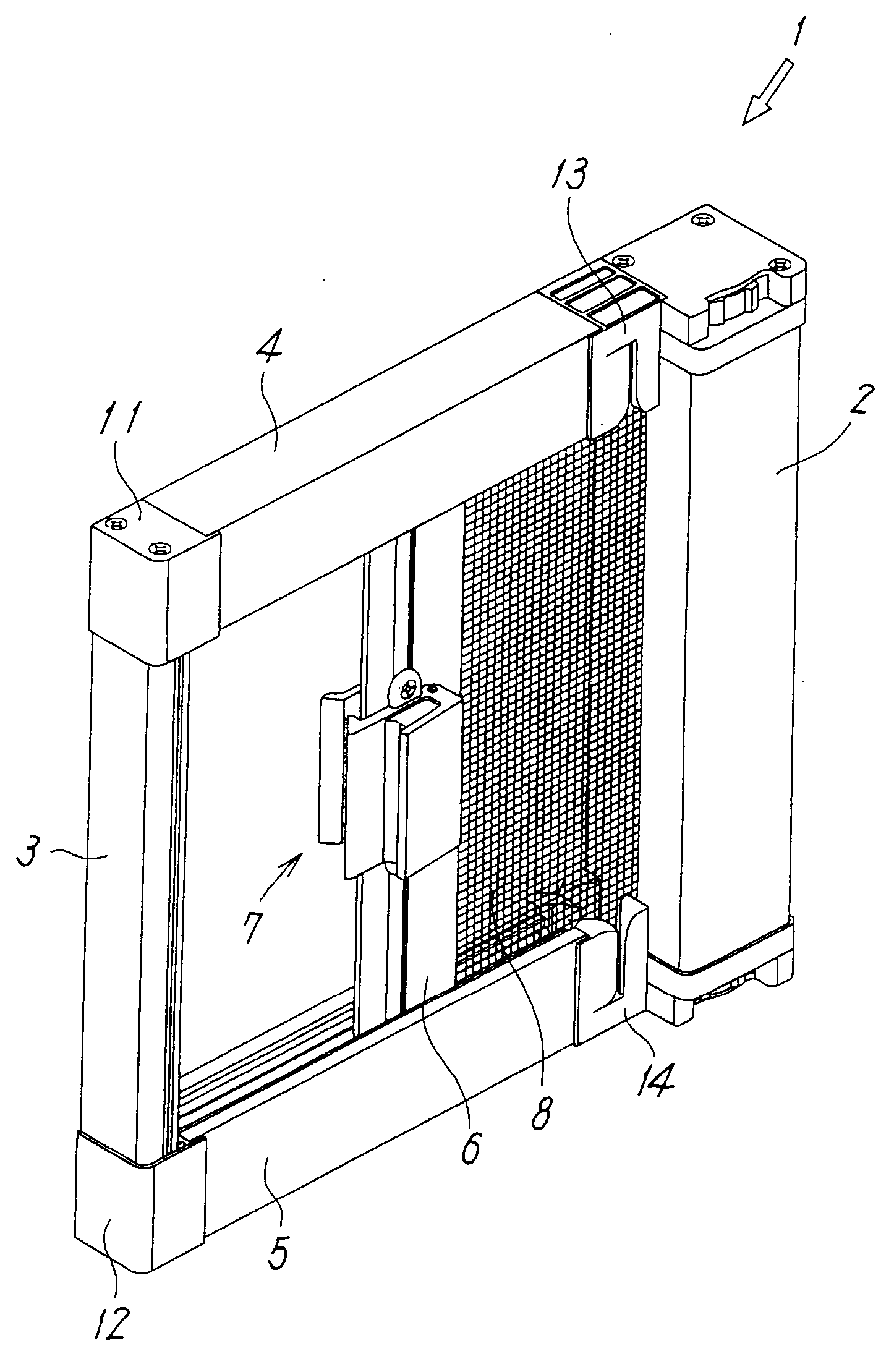
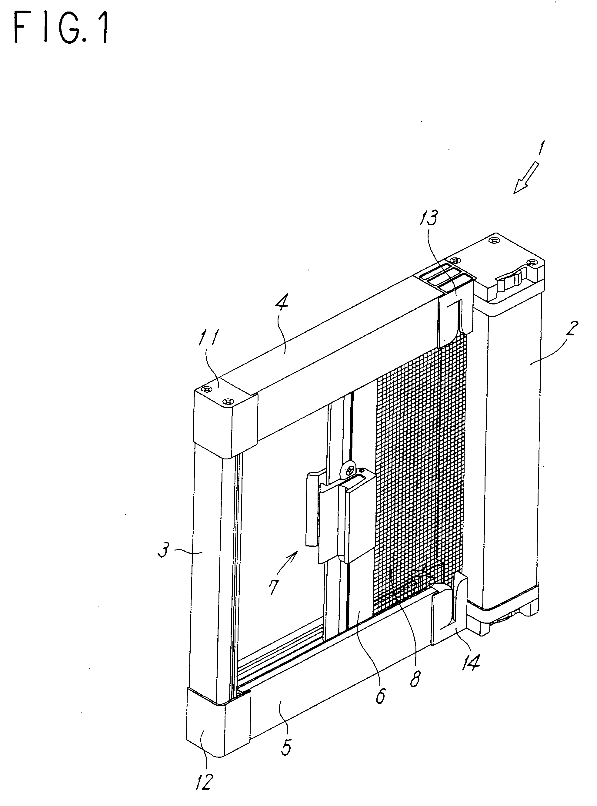
[0035] Embodiments of the present invention will now be described with reference to the drawings. FIGS. 1 to 5 illustrate a first embodiment in which a windable screen device according to the present invention is applied to a side-sliding fly-screen door.
[0036] Referring to FIGS. 1 and 2, a fly-screen door 1 includes a winding box 2 fixed to one of side-frames (not shown in the drawings) disposed along one side of an opening of a building; a stationary locking-frame member 3 fixed to the other side-frame (not shown in the drawings) disposed along the other side of the opening of the building; upper and lower guide rails 4 and 5 respectively mounted to upper and lower frames disposed along the upper and lower sides of the opening of the building; a screen 8, i.e. a fly-screen, which can be opened and closed by being moved along the upper and lower guide rails 4 and 5; a movable-frame member 6 whose one side is fixed to the screen 8 and which can be operated so as to open or close the...
second embodiment
[0054] FIGS. 12(a) and 12(b) illustrate a second embodiment in which the locking element 7 is provided in a windable double-sliding-screen device.
[0055] Although the locking-frame member 3 is fixed to an opening of a building in the single-sliding screen device described above, the double-sliding screen device of the second embodiment is provided with a second movable-frame member 60 in place of the stationary locking-frame member 3, such that the movable-frame member 60 functions as a movable locking-frame member. In this case, the hooking component 23 of the movable-frame member 6 is engageable with an engagement portion 61 provided in the second movable-frame member 60.
[0056] Like the movable-frame member 6, the second movable-frame member 60 has a long-plate structure provided with the attachment grooves 36, 43, and 44 which are T-shaped in cross-section. Although the second movable-frame member 60 basically has the same structure as the movable-frame member 6, the second movab...
PUM
 Abstract
Description
Claims
Application Information