Cutting elements formed from ultra hard materials having an enhanced construction

a cutting element and ultra-hard material technology, applied in cutting machines, layered products, transportation and packaging, etc., can solve the problems of premature failure of the cutting element and the drilling device including the same, poor thermal stability of the pcd cutting element, etc., to reduce or minimize unwanted delamination and/or spalling, improve the service life of the cutting element, and improve the effect of wear resistance and thermal stability

Inactive Publication Date: 2006-07-27
SMITH INT INC
View PDF7 Cites 217 Cited by
  • Summary
  • Abstract
  • Description
  • Claims
  • Application Information

AI Technical Summary

Benefits of technology

[0008] The diamond body further includes an intermediate layer that is joined to the uppermost layer and that comprises a plurality of bonded diamond crystals. The intermediate layer is specifically designed to have a wear resistance that is less than that of the uppermost layer remaining region to provide for the preferential wear of the intermediate layer relative to the uppermost layer, and to eliminate or resist any cracking during use. Such differential wear resistance can be achieved by using differently sized diamond grains to form the uppermost and intermediate layers and / or by using different diamond grain content.
[0010] Cutting elements constructed in accordance with the principles of this invention, when formed from PCD, provide improved properties of wear resistance and thermal stability when compared to conventional PCD cutting elements in a manner that reduces or minimizes unwanted delamination and / or spalling, thereby providing improved cutting element service life.

Problems solved by technology

PCD is known to suffer thermal degradation at a temperature starting at about 400° C. and extending to 1200° C. and, thus conventional PCD cutting elements are known to have poor thermal stability when exposed to operating temperatures approaching 700° C. Therefore, some of the techniques used for improving the wear resistance of PCD have focused at improving the thermal stability of the PCD.
While this technique is known to improve the thermal stability of the treated uppermost layer, PCD cutters that have been treated in this manner are known to suffer from delamination and spalling during use, leading to premature failure of the cutting element and the drilling device including the same.

Method used


Image

  • Cutting elements formed from ultra hard materials having an enhanced construction
  • Cutting elements formed from ultra hard materials having an enhanced construction
  • Cutting elements formed from ultra hard materials having an enhanced construction

Examples


first embodiment

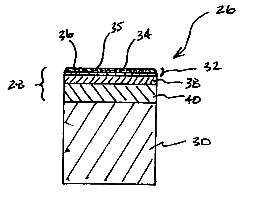
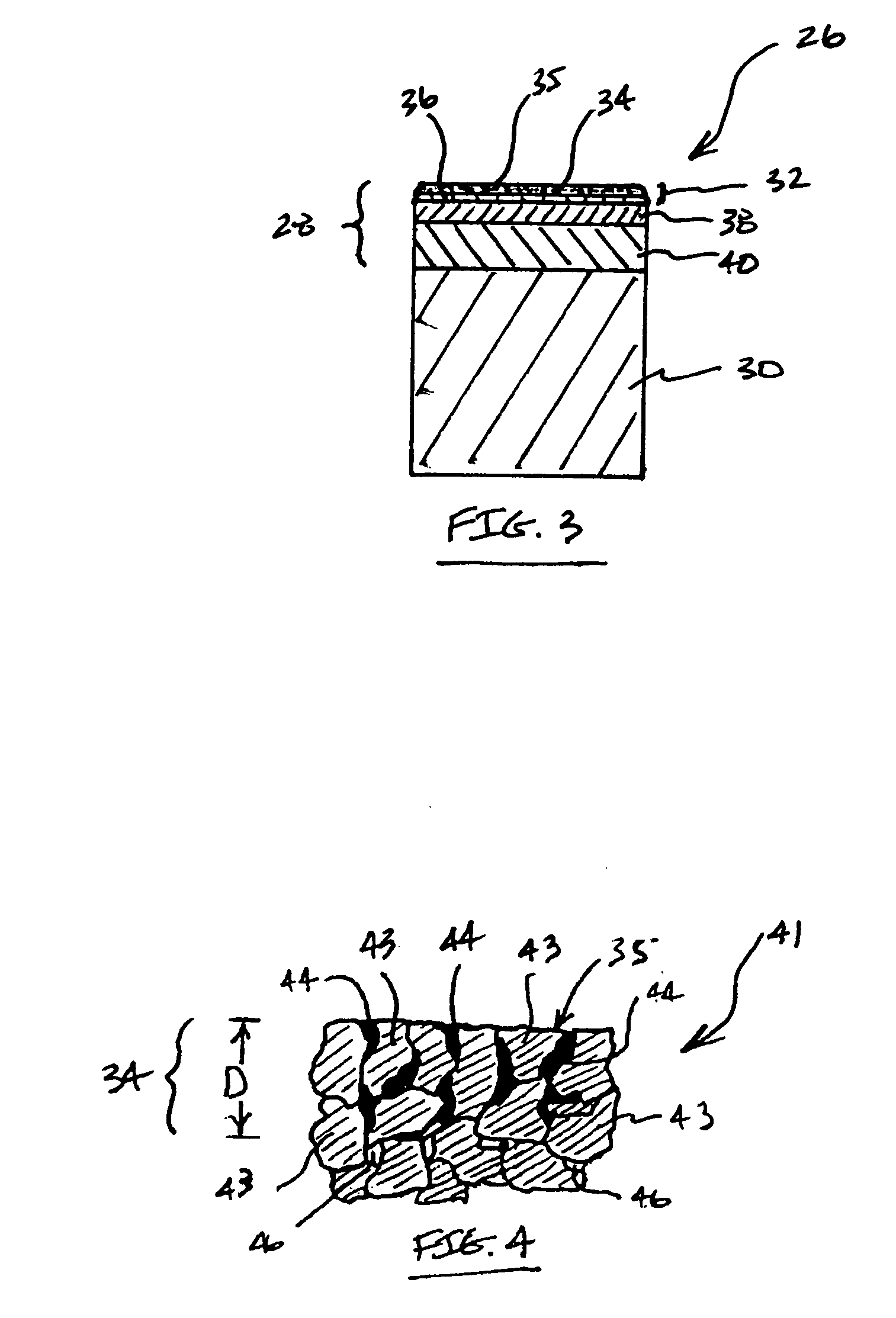
[0023]FIG. 3 illustrates a first embodiment cutting element 26 of this invention comprising, in its most general sense an ultra hard material body 28 that is sintered or otherwise attached to a substrate 30, e.g., a metallic substrate. In a preferred embodiment, the ultra hard material body comprises PCD. The PCD body comprises a number of different layers or regions that are joined to one another and that are each specially engineered to contribute specific properties to the overall construction. In this particular embodiment, the PCD body 28 includes an uppermost layer 32. The uppermost layer is formed from a PCD material that is capable of providing a high degree of wear resistance. In an example embodiment, the uppermost layer 32 comprises PCD that is formed using relatively tough / coarse-grade diamond grains.

[0024] In this example embodiment, the uppermost layer 32 includes an outer region 34 that includes an outer surface 35 that defines a working or cutting surface of the cutt...

second embodiment

[0057] Referring to FIGS. 3 and 5, the ultra hard bodies of the first and second embodiment cutter element of this invention are each attached to the substrate 30. Materials useful for forming substrates of this invention include those conventionally used as substrates for conventional PCD and PcBN compacts, such as those formed from metallic and cermet materials. In an example embodiment, the substrate is provided in a preformed state and includes a metal solvent catalyst that is capable of infiltrating into the adjacent diamond powder mixture, used for forming the lowermost layer or the intermediate layer, during HPHT processing to facilitate and provide a bonded attachment therewith. Suitable metal solvent catalyst materials include those selected from Group VIII elements of the Periodic table. A particularly preferred metal solvent catalyst is cobalt (Co). In a preferred embodiment, the substrate is formed from cemented tungsten carbide (WC—Co).

[0058] While cutter element embodi...


PUM

PropertyMeasurementUnit
particle sizeaaaaaaaaaa
grain sizeaaaaaaaaaa
depthaaaaaaaaaa

Abstract

Cutting elements of this invention include an ultra hard body joined with a metallic substrate. The body includes an uppermost layer comprising a plurality of bonded ultra hard crystals and interstitial regions, and that defines a body working surface. The uppermost layer includes an outer region that is relatively more thermally stable than a remaining portion of the uppermost layer. The body further includes an intermediate layer joined to the uppermost layer, comprising a plurality of bonded ultra hard crystals, and having a wear resistance less than that of the uppermost layer remaining region. The body may additionally include a lowermost PCD layer that is interposed between and attached to the intermediate layer and the substrate.

Description

FIELD OF THE INVENTION [0001] This invention generally relates to cutting elements formed from ultra hard materials and, more specifically, to polycrystalline diamond cutting elements having one or more layers that are specially engineered to provide an enhanced degree of cutting and / or thermal performance when compared to conventional polycrystalline diamond cutting elements, thereby providing an improved degree of service life in desired cutting and / or drilling applications. BACKGROUND OF THE INVENTION [0002] Cutting or wear elements formed from ultra hard materials such as polycrystalline diamond (PCD) used in applications such as with drill bits used for subterranean drilling are well known in the art. Such known cutting elements comprise PCD that is formed by combining synthetic diamond grains with a suitable solvent catalyst material to form a mixture. The mixture is subjected to processing conditions of extremely high pressure / high temperature (HPHT), where the solvent cataly...

Claims


Application Information

Patent Timeline
Patent Type & Authority Applications(United States)
IPC IPC(8): E21B10/55
CPCB22F7/06B22F2005/001B22F2998/00E21B10/567Y10T428/30B22F2207/03C22C26/00E21B10/46E21B10/52
Inventor BELNAP, JOHNMIDDLEMISS, STEWART
Owner SMITH INT INC
Why Eureka
Try Eureka