Control device for a four-wheel drive vehicle

a four-wheel drive, control device technology, applied in the direction of brake systems, transportation and packaging, gearing, etc., can solve the problems of unstable vehicle behavior, reduced cornering force generated by the rear tires, and inability to prevent oversteering after all, so as to maintain vehicle behavior stability

Inactive Publication Date: 2006-07-27
SUBARU CORP
View PDF16 Cites 23 Cited by
  • Summary
  • Abstract
  • Description
  • Claims
  • Application Information

AI Technical Summary

Benefits of technology

[0008] In view of the above circumstances, the object of the present invention is to provide a control device for a four-wheel drive vehicle for suppressing the transfer of excess driving force to the rear wheels so as to maintain the vehicle behavior stability even when the traction control is not effective.
[0010] By use of the control device for a four-wheel drive vehicle according the present invention, it is possible to maintain vehicle behavior stability since the transfer of excess driving force to the rear wheels is suppressed even when the traction control is not effective.

Problems solved by technology

However, if the traction control is not effective, the driving force is excessively transferred to the two rear wheels so that the cornering force generated by the rear tires tends to decrease.
Thus, the over-steering tendency cannot be prevented after all.
However, in the center differential mechanism wherein the torque distribution between the front and rear axles is controlled by means of a clutch that can vary the transfer capacity, reducing the engagement torque of the clutch may permit the transfer of excess driving force to the rear wheels, likely to cause unstable vehicle behaviors.

Method used


Image

  • Control device for a four-wheel drive vehicle
  • Control device for a four-wheel drive vehicle
  • Control device for a four-wheel drive vehicle

Examples


Embodiment Construction

[0018] Embodiments of the present invention are described below with reference to the accompanying drawings to facilitate understanding of the present invention.

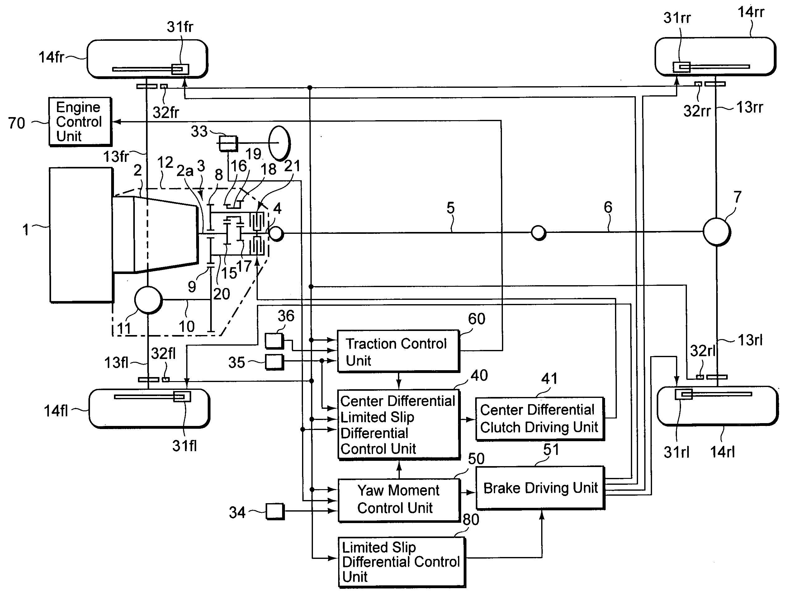
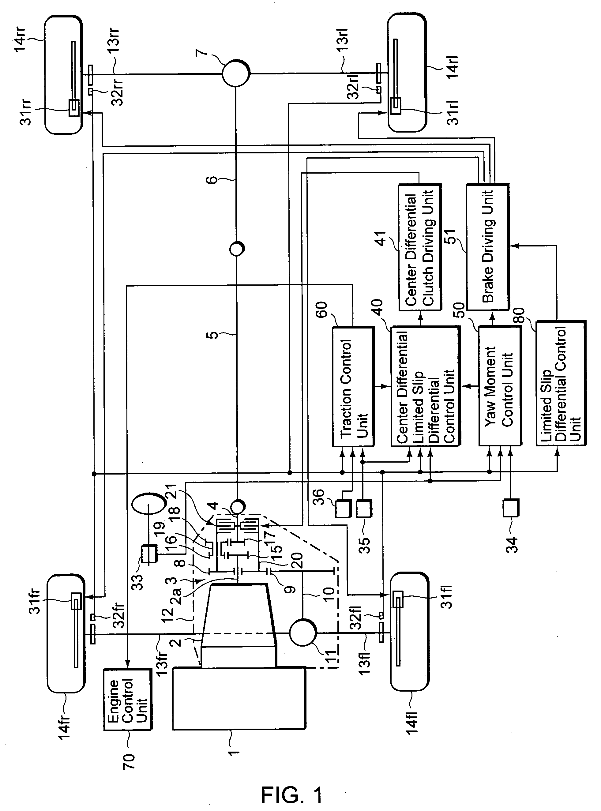
[0019] In FIG. 1, the reference numeral 1 refers to an engine mounted on the front of a vehicle. The driving force generated by the engine 1 is transmitted through an automatic transmission system 2 (shown including a torque converter and other parts) in the rear of the engine and through a transmission output axle 2a to a center differential system 3.

[0020] The driving force transmitted to the center differential system 3 is inputted to a rear wheel final reduction device 7 through a rear drive axle 4, a propeller shaft 5, and a drive pinion axle, as well as to a front wheel final reduction device 11 through a transfer drive gear 8, a transfer driven gear 9, and a front drive axle 10 which serves as a drive pinion axle. The automatic transmission system 2, the center differential system 3, and the front wheel final reduct...


PUM


Abstract

The objective of the present invention is to provide a control device for maintaining vehicle behavior stability by suppressing the transfer of excess driving force to the rear wheels even when the traction control is not effective. According to the present invention, there is provided a control device for a four-wheel drive vehicle, including: a yaw moment control unit for selecting a wheel based on a driving state and generating yaw moment on the vehicle by applying braking force to the selected wheel; a driving force control unit for identifying excess driving force based on the driving state and reducing the identified excess driving force; a limited slip differential control unit for limiting a differential between a front right wheel and a front left wheel; a front and rear driving force distribution control unit for controlling engagement torque of a clutch unit which varies torque distribution between front and rear axles via a center differential; and a switch unit for selecting an operation state or a non-operation state of the driving force control unit, wherein the front and rear driving force distribution control unit sets the engagement torque of the clutch unit at a value when the yaw moment control unit operates while the driving force control unit is in the non-operation state, the value being greater than that of the engagement torque of the clutch unit when the yaw moment control operates while the driving force control unit is in the operation state.

Description

CROSS REFERENCE TO RELATED APPLICATIONS [0001] This application claims priority under 35 U.S.C. 119 based upon Japanese Patent Application Serial No. 2005-018804, filed on Jan. 26, 2005. The entire disclosure of the aforesaid application is incorporated herein by reference. BACKGROUND OF THE INVENTION [0002] 1. Field of the Invention [0003] The present invention relates to a control device for a four-wheel drive vehicle, comprising yaw moment control for generating yaw moment on the vehicle, driving force control for suppressing excess driving force, and limited slip differential control for limiting differential motion between the right and left wheels. [0004] 2. Description of the Related Art [0005] Four-wheel drive vehicles manufactured in recent years are equipped with a number of vehicle behavior control devices such as yaw moment control for generating yaw moment on the vehicle, driving force control (traction control) for suppressing excess driving force, limited slip differe...

Claims


Application Information

Patent Timeline
Patent Type & Authority Applications(United States)
IPC IPC(8): B60K17/35B60T8/1755
CPCB60K17/3462B60K17/35B60K23/0808B60T8/1755B60T8/1769B60T2201/14B60W10/14B60W10/16B60W10/184
Inventor KUROSAWA, JUNICHIINOUE, KOUICHITANAKA, YOSHIYUKI
Owner SUBARU CORP
Why Eureka
Try Eureka