Suspension and electro-acoustic transducer using the suspension

Active Publication Date: 2006-07-27
PANASONIC CORP
View PDF13 Cites 22 Cited by
  • Summary
  • Abstract
  • Description
  • Claims
  • Application Information

AI Technical Summary

Problems solved by technology

Non-linearity of the compliance of supporting force, which is caused by a shape of suspension 1, causes distortion particularly in reproduction of a low tone area where amplitude becomes large.
Compliance of the suspension becomes difficult t

Method used


Image

  • Suspension and electro-acoustic transducer using the suspension
  • Suspension and electro-acoustic transducer using the suspension
  • Suspension and electro-acoustic transducer using the suspension

Examples


first exemplary embodiment

[0025] The first exemplary embodiment of the present invention is demonstrated hereinafter with reference to FIG. 1 through FIG. 5.

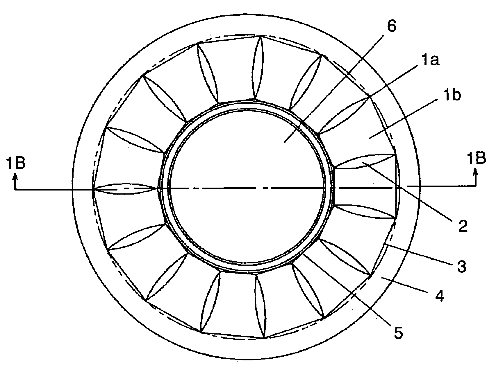
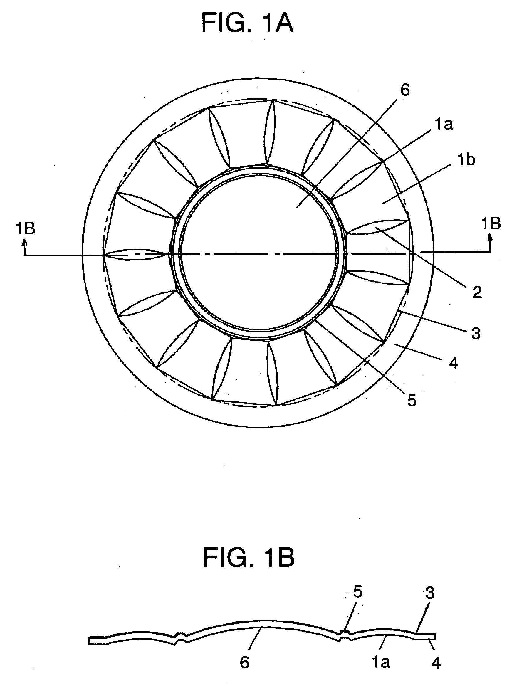
[0026]FIG. 1A is a plan view of a suspension in accordance with the first exemplary embodiment of the present invention. FIG. 1B is a sectional view of FIG. 1A taken along the line 1B-1B. FIG. 2A is a perspective view of FIG. 1A. FIG. 2B is an enlarged sectional view of FIG. 2A taken along the line 2B-2B. FIG. 2C is an enlarged sectional view of FIG. 2A taken along the line 2C-2C. FIG. 3 is a sectional view of an electro-acoustic transducer using the suspension. FIG. 4 is a graph showing a force-displacement characteristic of the suspension in vibration. FIG. 5 shows a condition of the suspension in vibration.

[0027] In FIGS. 1A and 1B, roll sections 1b are disposed radially at a periphery of diaphragm 6 so as to form suspension 1a. Connecting part 3 between frame fixing part 4 and vibration system fixing part 5 is formed linear. Adjacent roll sections ...

second exemplary embodiment

[0040] The second exemplary embodiment of suspension device 20 of the present invention is demonstrated hereinafter with reference to FIGS. 6A and 6B.

[0041]FIG. 6A is a plan view of suspension device 20 in accordance with the second exemplary embodiment of the present invention. FIG. 6B is a sectional view of FIG. 6A taken along the line 6B-6B.

[0042] Only different point between the first embodiment and the second embodiment is described hereinafter with reference to FIGS. 6A and 6B. Suspensions 1c and 1d each have the same shape as suspension 1a, and are fixed to voice coil 10. Suspension 1c is placed above suspension 1d at a certain distance. Suspension device 20 has suspensions 1c and 1d. Suspension 1c may be fixed to or integrally molded with diaphragm 6.

third exemplary embodiment

[0043] The third exemplary embodiment of suspension device 20 of the present invention is demonstrated hereinafter with reference to FIGS. 7A and 7B.

[0044]FIG. 7A is a plan view of suspension device 20 in accordance with the third exemplary embodiment of the present invention. FIG. 7B is a sectional view of FIG. 7A taken along the line 7B-7B. Suspension device 20 has suspensions 1c and 1d. Suspensions 1c and 1d each have the same shape as suspension 1a, and suspension 1c is shifted from suspension 1d by approximately ½ of width “L” of the roll section in a rotating direction (i.e., a periphery direction).

[0045] In other words, suspensions 1c and 1d are disposed in a substantially vertical direction, and one of suspensions 1c and 1d is rotated by ½ of a width of the roll section with respect to an axis in the periphery direction. Generation of rolling in driving can be prevented when the suspension is mounted in an electro-acoustic transducer.

[0046] Suspensions 1c and 1d are fixed...


PUM


Abstract

A suspension (1a) includes a plurality of roll sections (1b) each of which has a semicylindrical shape in a cross section. The roll sections (1b) are disposed side by side based on a straight line connecting two points on an inner periphery or an outer periphery. The roll sections (1b) form a closed loop in a manner that a roll section (1b) of the roll sections (1b) being disposed first adjoins a roll section (1b) of the roll sections (1b) being disposed last. Adjacent roll sections (1b) are coupled with each other through a boundary section (2) forming a continuous three dimensional curved surface. A linearity of compliance improves, and generation of distortion or rolling is restricted using the suspension (1a).

Description

TECHNICAL FIELD [0001] The present invention relates to a suspension used in an apparatus for reproducing a sound such as a voice, music or a dial tone, and an electro-acoustic transducer using the same. BACKGROUND ART [0002] A conventional electro-acoustic transducer is demonstrated hereinafter with reference to FIGS. 8, 9A and 9B. FIG. 8 is a sectional view of the electro-acoustic transducer. FIG. 9A is a plan view of a diaphragm. FIG. 9B is a sectional view of FIG. 9A taken along the line 9B-9B. In FIG. 8, diaphragm 6 generates aerial vibration. Diaphragm 6 is fixed to frame 11 by frame fixing part 4 through suspension 1 which has vibrating functions and supporting functions. Suspension 1 is of a semicylindrical shape in a cross section and uniform in a circumference direction. Diaphragm 6 is coupled with voice coil 10. Voice coil 10 is placed within magnetic gap 9 of magnetic circuit 8 which is provided at the middle of the frame 11 and formed of plate 13, magnet 14 and yoke 15....

Claims


Application Information

Patent Timeline
IPC IPC(8): H04R7/00H04R7/18H04R7/20
CPCH04R7/18H04R7/20H04R2307/207H04R9/043
Inventor HONDA, KAZUKISANO, KOJIOMORI, TATSUYA
Owner PANASONIC CORP
Why Eureka
Try Eureka