Apparatus for direct plating on resistive liners

Inactive Publication Date: 2006-07-27
IBM CORP
View PDF10 Cites 11 Cited by
  • Summary
  • Abstract
  • Description
  • Claims
  • Application Information

AI Technical Summary

Benefits of technology

[0011] The measuring device of the apparatus is not limited and can include one or more reference electrodes, a light source (such as a laser or light-emitting diode) and at least one photo detector (such as a photodiode) to measure the reflectivity of the at least one light sou

Problems solved by technology

However, these methods apply only in the case where a sufficient plating overpotential exists over the whole substrate surface, from edge to center.
In the case of thin copper seeds (5-50 nm), the sheet resistance is still low enough to ensure deposition over the whole substrate surface, although with a non-uniform growth rate in the case of a primary current distribution.
Additionally, too low current or overpotential results in a low density of nucleation sites leading to powdery, poorly adherent deposits.

Method used


Image

  • Apparatus for direct plating on resistive liners
  • Apparatus for direct plating on resistive liners
  • Apparatus for direct plating on resistive liners

Examples


Embodiment Construction

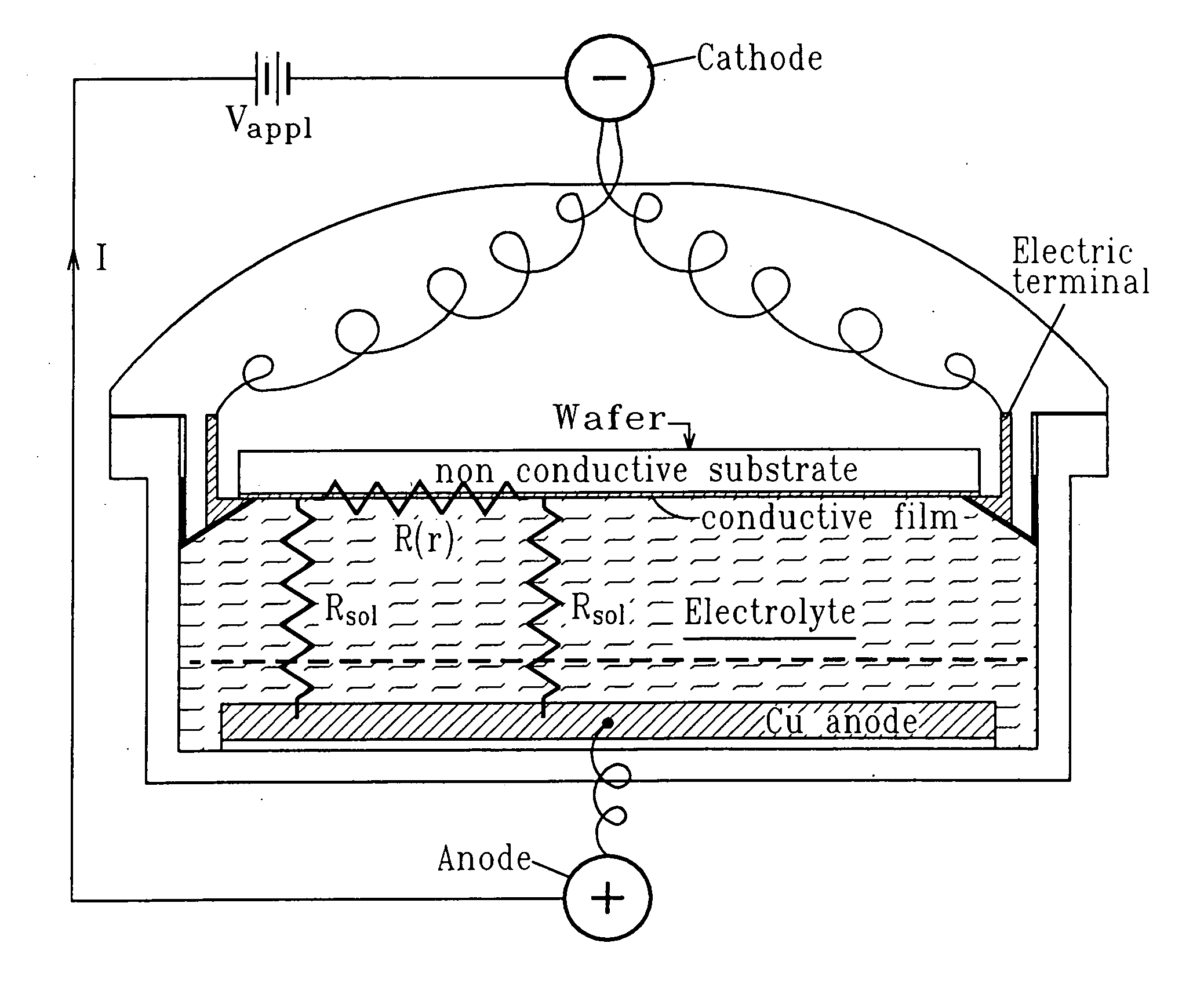
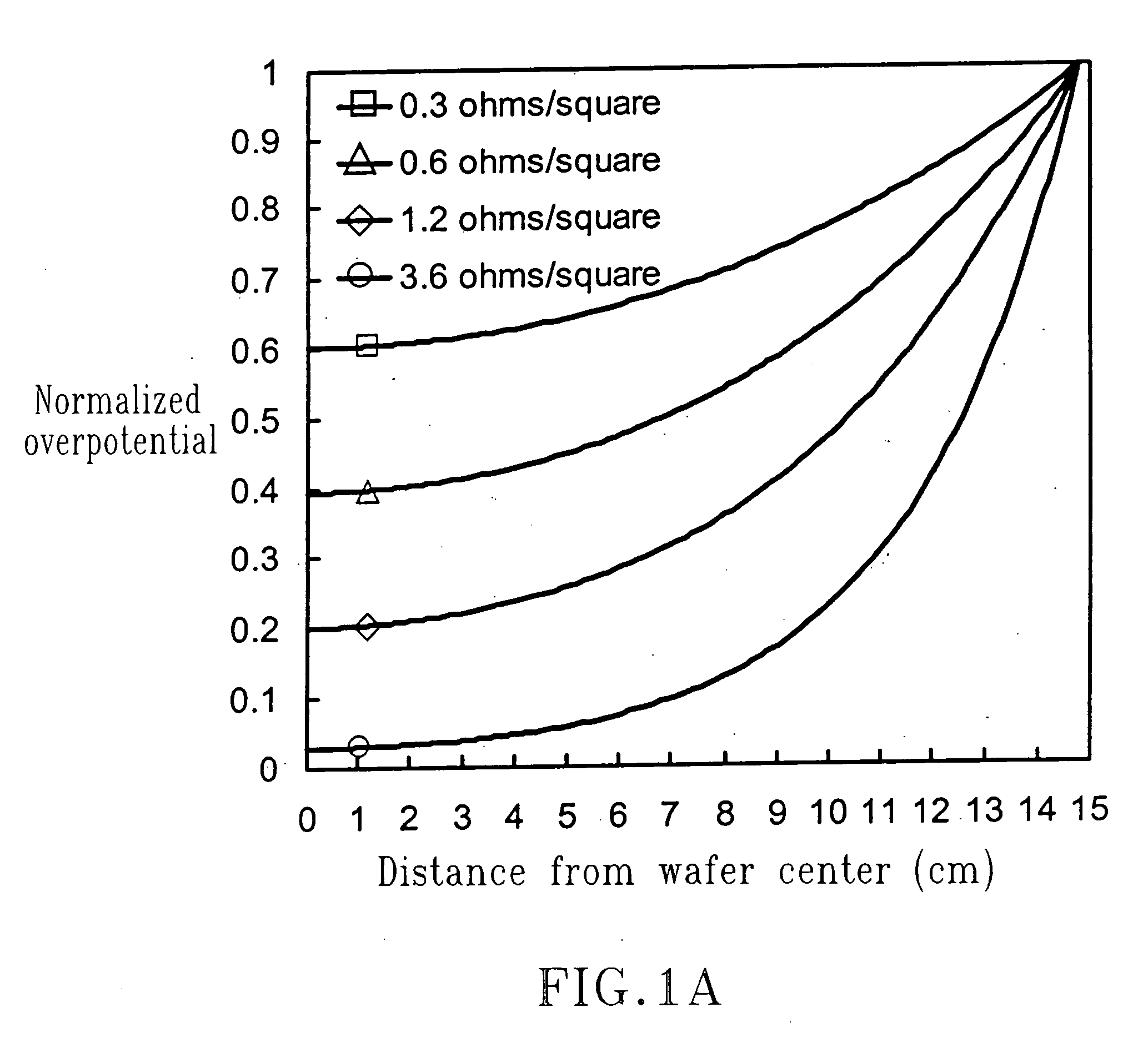
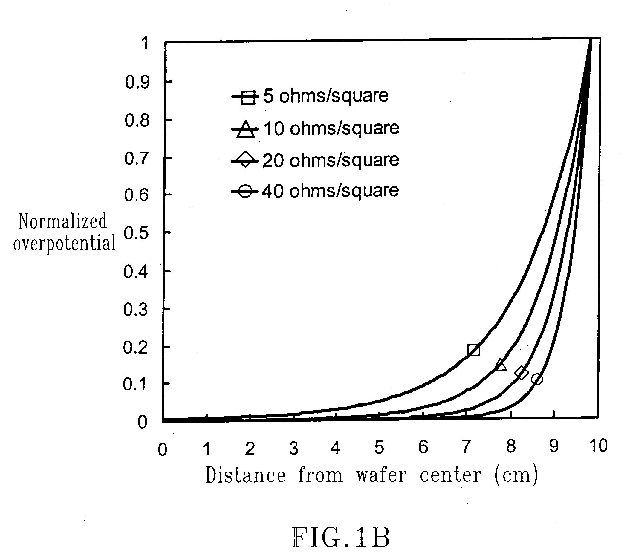
[0029] U.S. Published Application No. 2004 / 0069648 A1, the entire disclosure of which is incorporated herein by reference, discloses a method for the direct electroplating of a relatively low resistive metal, such as copper, on a resistive substrate. That method allows plating of copper directly on at least one liner layer, where the liner layer(s) act as a diffusion barrier for copper into the dielectric. These diffusion barrier layers typically have a sheet resistance, Rs, which can be several orders of magnitude higher than for currently used copper seed layers. For example, a typical diffusion barrier layer sheet resistance may be in the range of 5 to 300Ω / square, whereas copper seed layers may have a resistance in the range of 1 to 3Ω / square.

[0030] The method disclosed in U.S. Published Application No. 2004 / 0069648 A1 can be described as direct plating or seedless plating. This method is based on the fundamental concept that the driving force for plating, known as the overpote...


PUM

PropertyMeasurementUnit
Thicknessaaaaaaaaaa
Thicknessaaaaaaaaaa
Thicknessaaaaaaaaaa

Abstract

An apparatus for direct electroplating of a conductive material, such as copper, on resistive liners or substrates is provided. The apparatus includes an integrated in-situ measuring system to follow the actual progress of the front of the conductive material during plating. Feed-back of this information to a power supply allows for more precise control of the effective current density during plating.

Description

FIELD OF THE INVENTION [0001] The present invention relates to electroplating an electrically conductive material such as a relatively low resistive metal and especially copper onto a platable resistive metal barrier layer or stack of layers. More particularly, the present invention relates to an apparatus for directly plating onto the resistive metal without the need of a seed or catalyst layer, and especially without the need of a copper seed layer (even though a thin seed may be present, e.g. about 1.ANG.-about 10.ANG.). The present invention makes it possible to form a continuous and relatively uniform layer by growing a thin film from the edge of the surface to be plated towards its center by controlling the conditions of the current or voltage being applied. BACKGROUND OF THE INVENTION [0002] The current damascene plating process and especially that for copper requires a copper seed as a conductive layer on top of the highly resistive barrier liner which covers the underlying ...

Claims


Application Information

Patent Timeline
IPC IPC(8): C25D21/12
CPCC25D21/12H01L21/2885H01L22/26H01L2924/0002H01L2924/00
Inventor VEREECKEN, PHILIPPE M.ANDRICACOS, PANAYOTISDELIGIANNI, HARIKLIAKWIETNIAK, KEITH T.ANDRICACOS, CALIOPI
Owner IBM CORP
Why Eureka
Try Eureka