Friction stir welding apparatus

a friction stir and welding apparatus technology, applied in the direction of soldering apparatus, manufacturing tools, auxillary welding devices, etc., can solve the problems of low tolerance between prior art poor run-out tolerance or close fit between pin and shoulder, impracticality of maintaining tight tolerance between pin and shoulder tools, etc., to achieve better friction stir welds, reduce tolerances, and facilitate replacement of the two tools

Active Publication Date: 2006-07-27
THE BOEING CO
View PDF10 Cites 24 Cited by
  • Summary
  • Abstract
  • Description
  • Claims
  • Application Information

AI Technical Summary

Benefits of technology

[0008] The friction stir welding apparatus of the invention provides a novel tool-in-tool holding system that, when combined with an electromechanical coaxial spindle design of a stir welding machine, is ideal for the production friction stir welding process. The apparatus of the invention comprises a friction stir welding pin tool that is mounted through a center bore of a friction stir welding shoulder tool. The coaxial mounting of the two tools enables both the pin tool and shoulder tool to be engaged and held by two separate standard commercially available tool holders. This facilitates the installation and removal of each of the pin and shoulder tools from the friction stir welding apparatus, and thereby increases the available production time of the apparatus.
[0009] The shoulder tool holder is modified to allow the pin tool to extend through both the shoulder tool center bore and the shoulder tool holder. The use of two separate holders for the pin and shoulder tools utilizes the overall accurate positioning of the pin and shoulder spindles of the apparatus. The use of two off-the-shelf tool holders for holding the pin and shoulder tools separately is a unique alternative to the prior art method of holding the prior art friction stir welding pin and shoulder assemblies that allows for tighter welding process tolerances, decreases the run-out of the pin tool and shoulder tool, and allows for shorter, predictable tool changes and more accurate friction stir welds. Pin tool and shoulder tool changes are predictable, man-hours are decreased, tool accuracy and tool relationships are very accurate, welding tolerances are increased and are more predictable. In addition, the wear and tear on expensive spindles is decreased because the run-out of the friction stir welding pin tool and shoulder tool is reduced.
[0014] With the friction stir welding pin tool held to the pin tool spindle by the pin tool holder, and with the friction stir welding shoulder tool held to the shoulder tool spindle by the shoulder tool holder, the pin tool extends axially through the center bore of the shoulder tool holder and through the center bore of the shoulder tool. Rotation of the pin tool spindle and the shoulder tool spindle rotates both the pin tool and shoulder tool in the same or opposite directions, and at the same or different rates of rotation. In addition, relative axial movement between the pin tool spindle and the shoulder tool spindle moves the pin tool axially through the center bore of the shoulder tool. This enables the distal end of the pin tool to be extended outwardly from the distal end of the shoulder tool to produce the relatively positioned pin and shoulder surfaces used in the friction stir welding processes, and enables the retraction of the pin into the shoulder tool surface when the welding process is completed.
[0015] The tool-in-tool arrangement of the pin tool and shoulder tool enables the use of separate spindles and separate tool holders for the friction stir welding tools. This also enables reduced tolerances between the tools that produces better friction stir welds, and enables easier replacement of the two tools that reduces man-hours and downtime of the friction stir welding apparatus.

Problems solved by technology

Due to the existing designs of friction stir welding machine spindles and the present techniques of installing retractable pin and shoulder friction stir welding tools on the spindles, maintaining a tight tolerance between the pin and shoulder tools is impractical.
The tolerances between prior art pin and shoulder tools are low, and therefore the run-out tolerance or the close fit between the pin and shoulder is generally very poor.
This results in inaccurate welds produced by the tools.
In addition, the time required to change the pin and shoulder friction stir welding tools in a spindle in the current configuration of friction stir welding machines is very slow and costly.

Method used


Image

  • Friction stir welding apparatus
  • Friction stir welding apparatus
  • Friction stir welding apparatus

Examples


Embodiment Construction

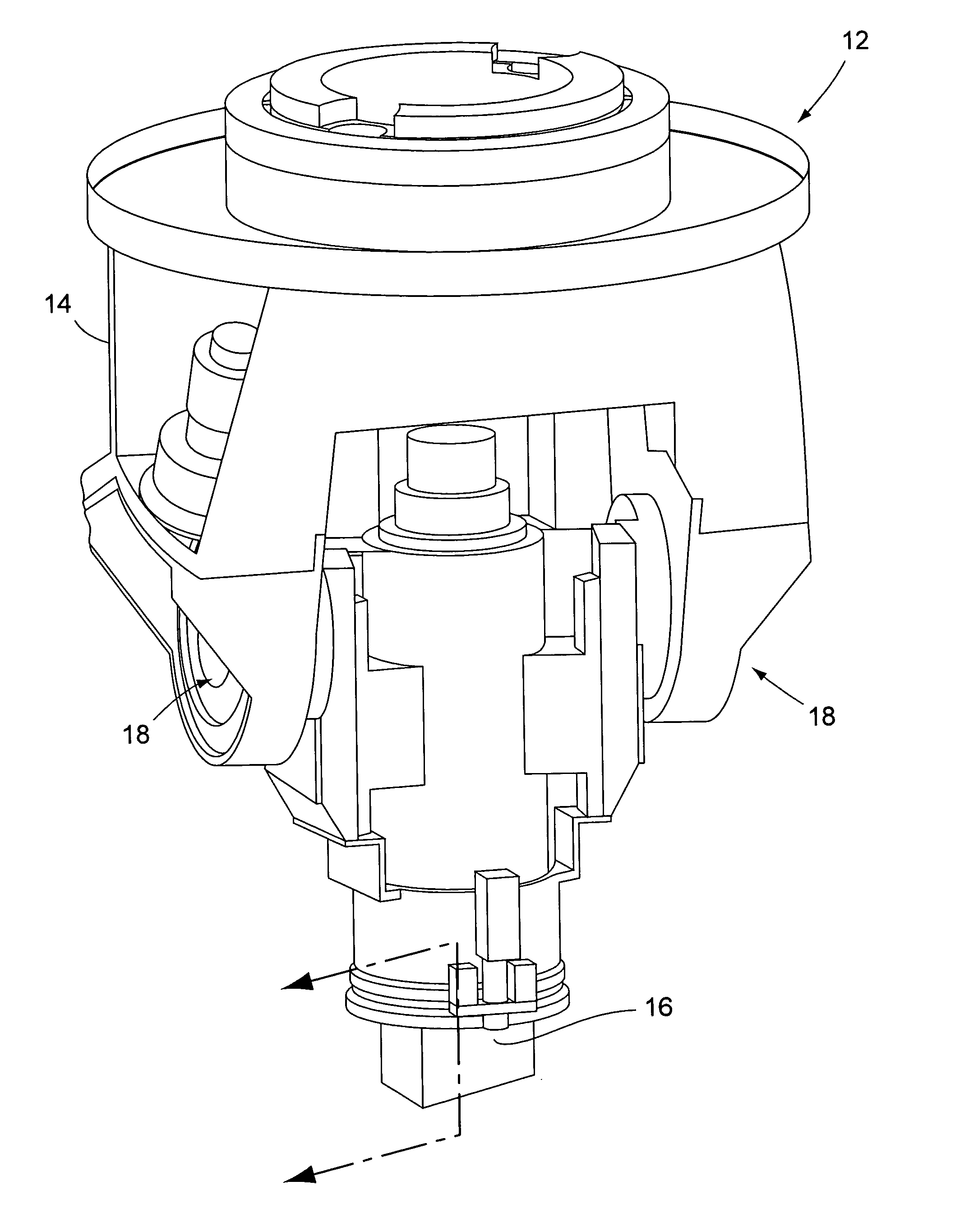
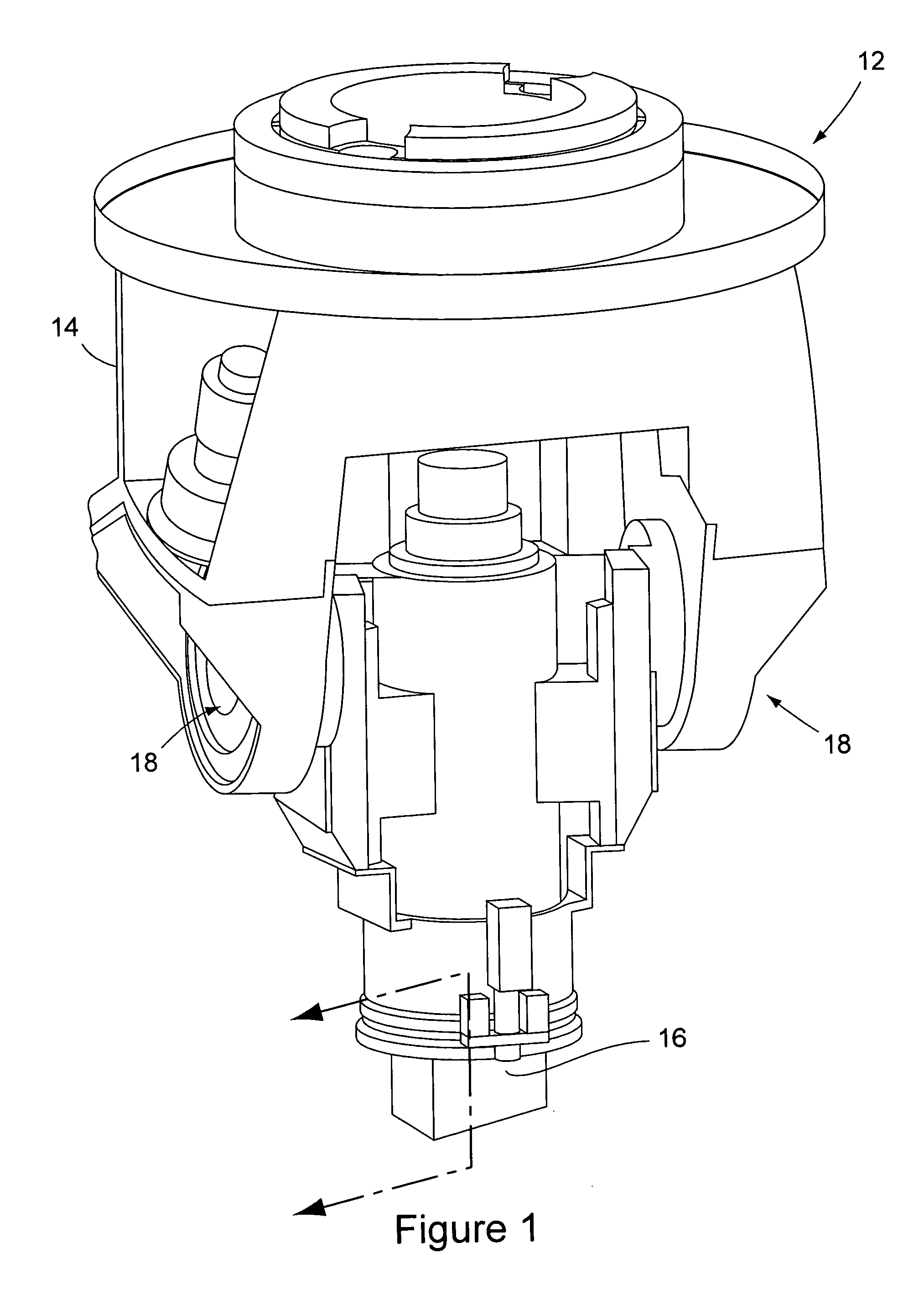
[0021]FIG. 1 shows a portion of a conventional friction stir welding machine 12, for example a milling machine, that has been modified by the tool-in-tool apparatus of the present invention to perform friction stir welding operations. Because various types of milling machines exist and their constructions are well known, the component parts of the machine 12 shown in FIG. 1 will not be described in detail. The machine 12 includes a spindle carriage 14 that supports the friction stir welding tool-in-tool apparatus of the invention over materials to be welded (not shown). As is conventional, the machine 12 is capable of moving the materials to be welded laterally relative to the spindle carriage 14 in performing the welding operation. The spindle carriage 14 suspends a spindle housing 16 from pivot assemblies 18. The spindle housing 16 contains the friction stir welding tool-in-tool apparatus of the invention. The connection of the spindle housing 16 to the carriage 14 by the pivot as...


PUM

PropertyMeasurementUnit
lengthaaaaaaaaaa
rate of rotationaaaaaaaaaa
rotationaaaaaaaaaa

Abstract

A friction stir welding apparatus has a novel tool-in-tool construction where a friction stir welding pin tool extends through a center bore of a friction stir welding shoulder tool and is moveable axially and rotationally relative to the shoulder tool. The pin tool and shoulder tool both have their own dedicated tool holders and spindles that enable the tools to rotate and move axially relative to each other and enable easy replacement of each of the tools.

Description

BACKGROUND OF THE INVENTION [0001] (1) Field of the Invention [0002] The present invention pertains to a friction stir welding apparatus in which a friction stir welding pin tool is received in a center bore of a friction stir welding shoulder in a tool-in-tool arrangement. [0003] (2) Description of the Related Art [0004] Friction stir welding is a recently developed method of welding that involves joining two sheets of metal along a weld line without fusing the metal of the sheets and without the use of welding filler materials. The welds are created by the combination of frictional heating of the metal by a rotating tool and mechanically deforming the metal with the rotating tool. The tool is typically constructed of a metal that is harder than the metal being friction stir welded. The tool has a cylindrical section with a circular distal end surface. The circular distal end surface of the tool is typically known as the “shoulder surface” of the tool. A smaller cylindrical section...

Claims


Application Information

Patent Timeline
Patent Type & Authority Applications(United States)
IPC IPC(8): B23K20/12
CPCB23K20/125
Inventor BURTON, KURT A.MATLACK, MIKE P.
Owner THE BOEING CO
Why Eureka
Try Eureka