System for assuring engagement of a hydromatic brake on a drilling or well service rig

a technology for hydromatic brakes and drilling rigs, which is applied in the field of hydromatic brake systems, can solve the problems of increasing the strain on the conventional brake drum, requiring a great deal of non-productive time and manpower, and increasing the string of pipes

Active Publication Date: 2006-07-27
KEY ENERGY SERVICES
View PDF13 Cites 24 Cited by
  • Summary
  • Abstract
  • Description
  • Claims
  • Application Information

AI Technical Summary

Problems solved by technology

While the operation of drilling an oil well has long been performed automatically by a drilling rig, there are operations in connection with oil well drilling or oil well servicing which require a great deal of non-productive time and man power.
While running lengths of pipe, it is obvious that as more and more lengths are run into the hole, the heavier and heavier the string of pipe becomes.
This puts an ever increasing strain on conventional brake drums of the cable hoist system, sometimes leading to brake failure or brake inefficiency due to heating while tripping into the hole.
As disk assist brakes are installed on remanufactured rigs, algorithms are being developed to control the speed throughout the range of downward block travel, but these algorithms are not currently being implemented.
Because the conventional drum brakes are self energizing, they are difficult to use to finely control downward speeds.
Hot brakes have control issues, resulting in part from band stretching and when the drums get out of round.
As the brakes heat, the rig has a nozzle system that is designed to cool the bands down, however this system has it problems too.
Heat and water changes metallurgy and causes corrosion.
This can lead to component failure and general brake failure.
One drawback of the hydromatic is the slowing down of the running speed.
When the energy of the downward moving block is transferred to the brake, the rig experiences a loss of freefall and therefore a slowing effect.
If he is in a hurry to trip into the hole, he is more likely to delay the brake engagement.

Method used


Image

  • System for assuring engagement of a hydromatic brake on a drilling or well service rig
  • System for assuring engagement of a hydromatic brake on a drilling or well service rig
  • System for assuring engagement of a hydromatic brake on a drilling or well service rig

Examples


Embodiment Construction

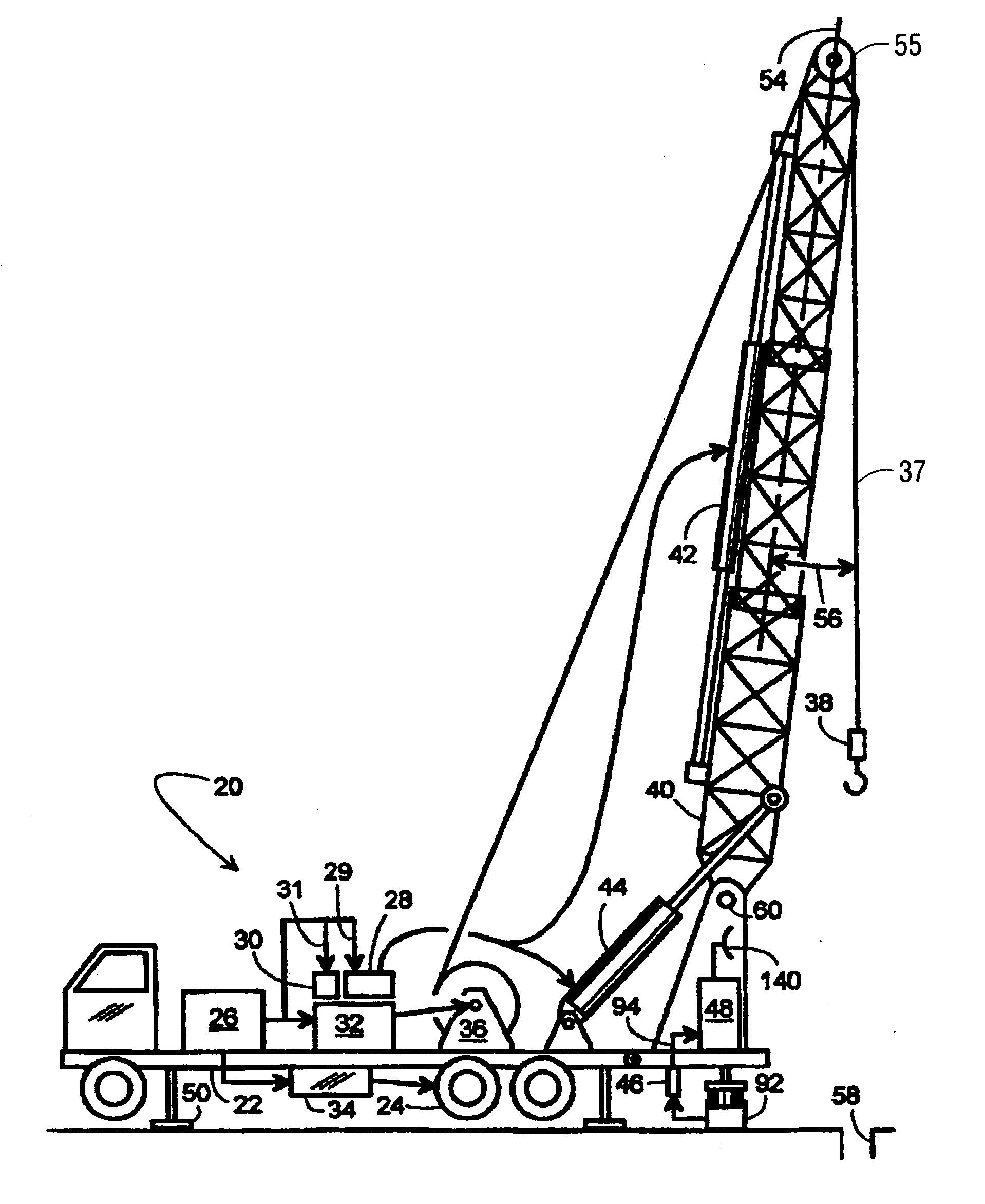
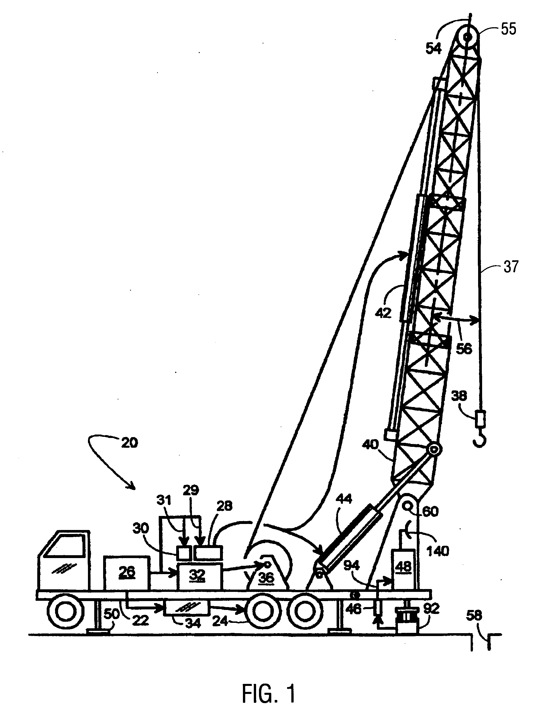
[0012] Referring to FIG. 1, a retractable, self-contained workover rig 20 is shown to include a truck frame 22 supported on wheels 24, an engine 26, a hydraulic pump 28, an air compressor 30, a first transmission 32, a second transmission 34, a variable speed hoist 36, a block 38, an extendible derrick 40, a first hydraulic cylinder 42, a second hydraulic cylinder 44, a monitor 48, and retractable feet 50. Engine 26 selectively couples to wheels 24 and hoist 36 by way of transmissions 34 and 32, respectively. Engine 26 also drives hydraulic pump 28 via line 29 and air compressor 30 via line 31. Compressor 30 powers a pneumatic slip (not shown), and pump 28 powers a set of hydraulic tongs (not shown). Pump 28 also powers cylinders 42 and 44 that respectively extend and pivot derrick 40 to selectively place derrick 40 in a working position (FIG. 1) and in a retracted position (not shown). In the working position, derrick 40 is pointed upward, but its longitudinal centerline 54 is angu...


PUM


Abstract

The present invention provides an automatic system for engaging the hydromatic brake on a drilling rig or a service rig. This system monitors both the hook load and traveling block velocity, and uses an electrical solenoid to activates the hydromatic when either the hook load or rotating drum velocity exceeds a maximum value, requiring hydromatic brake engagement.

Description

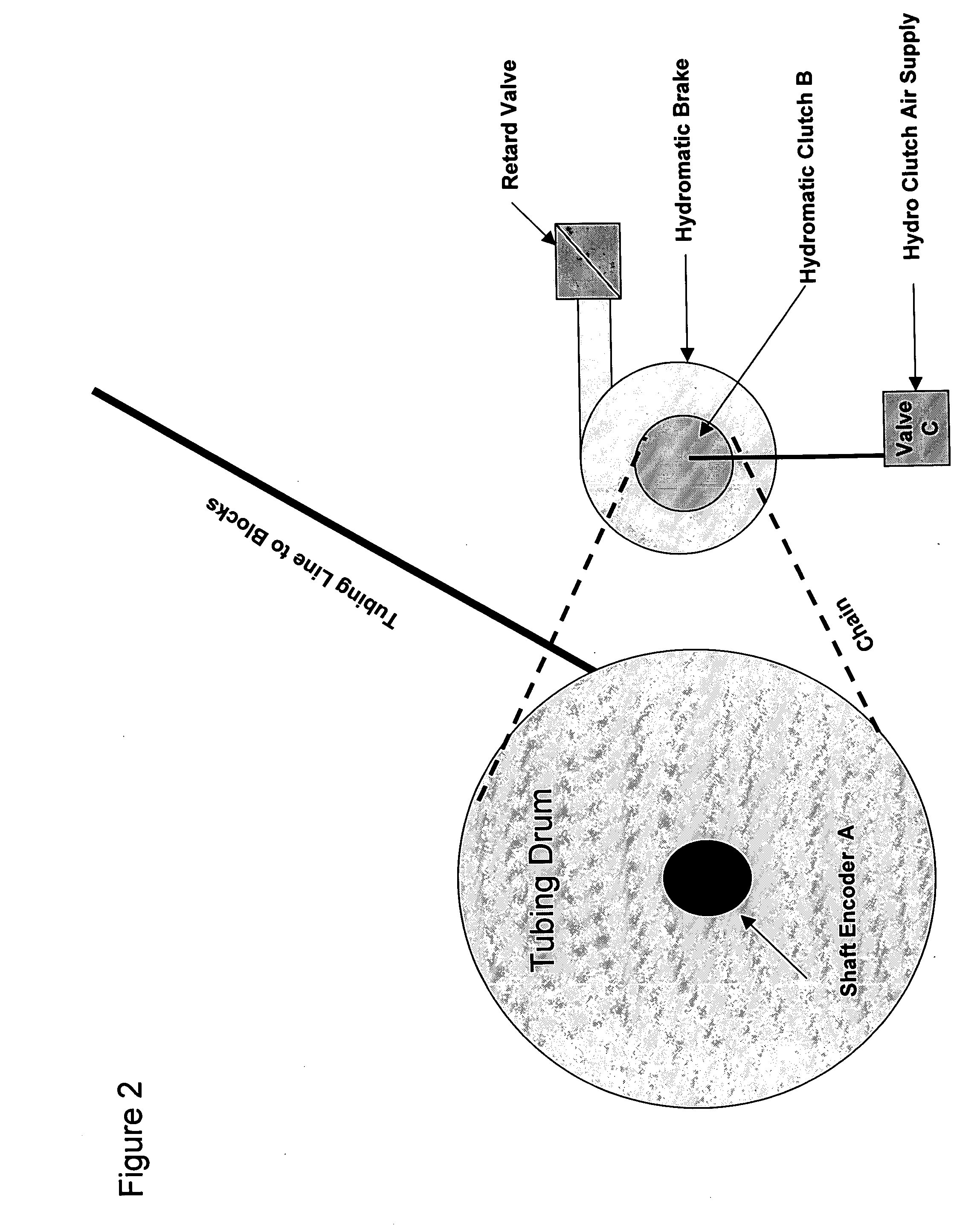
BACKGROUND OF THE INVENTION [0001] This invention relates to rigs used in oil well operations. Although it is primarily directed to service rigs used in the maintenance and overhaul of existing oil wells, it might also be adapted to use in association with rigs for drilling new oil wells. [0002] While the operation of drilling an oil well has long been performed automatically by a drilling rig, there are operations in connection with oil well drilling or oil well servicing which require a great deal of non-productive time and man power. In the case of a drilling rig it is frequently necessary to pull the drill string out of the hole (“tripping out”) to replace the bit and to run the drill pipe back into the hole. After an oil drilling rig drills a well and installs the well casing, the rig is dismantled and removed from the site. From that point on, a mobile repair unit, or workover rig, is typically used to service the well. Servicing includes, for example, installing and removing ...

Claims


Application Information

Patent Timeline
Patent Type & Authority Applications(United States)
IPC IPC(8): B66D1/48
CPCE21B19/008
Inventor NEWMAN, FREDERIC M.
Owner KEY ENERGY SERVICES
Why Eureka
Try Eureka