

Planar inverted f antenna
- Summary
- Abstract
- Description
- Claims
- Application Information
AI Technical Summary
Benefits of technology
Problems solved by technology
Method used
Image

Examples
first embodiment
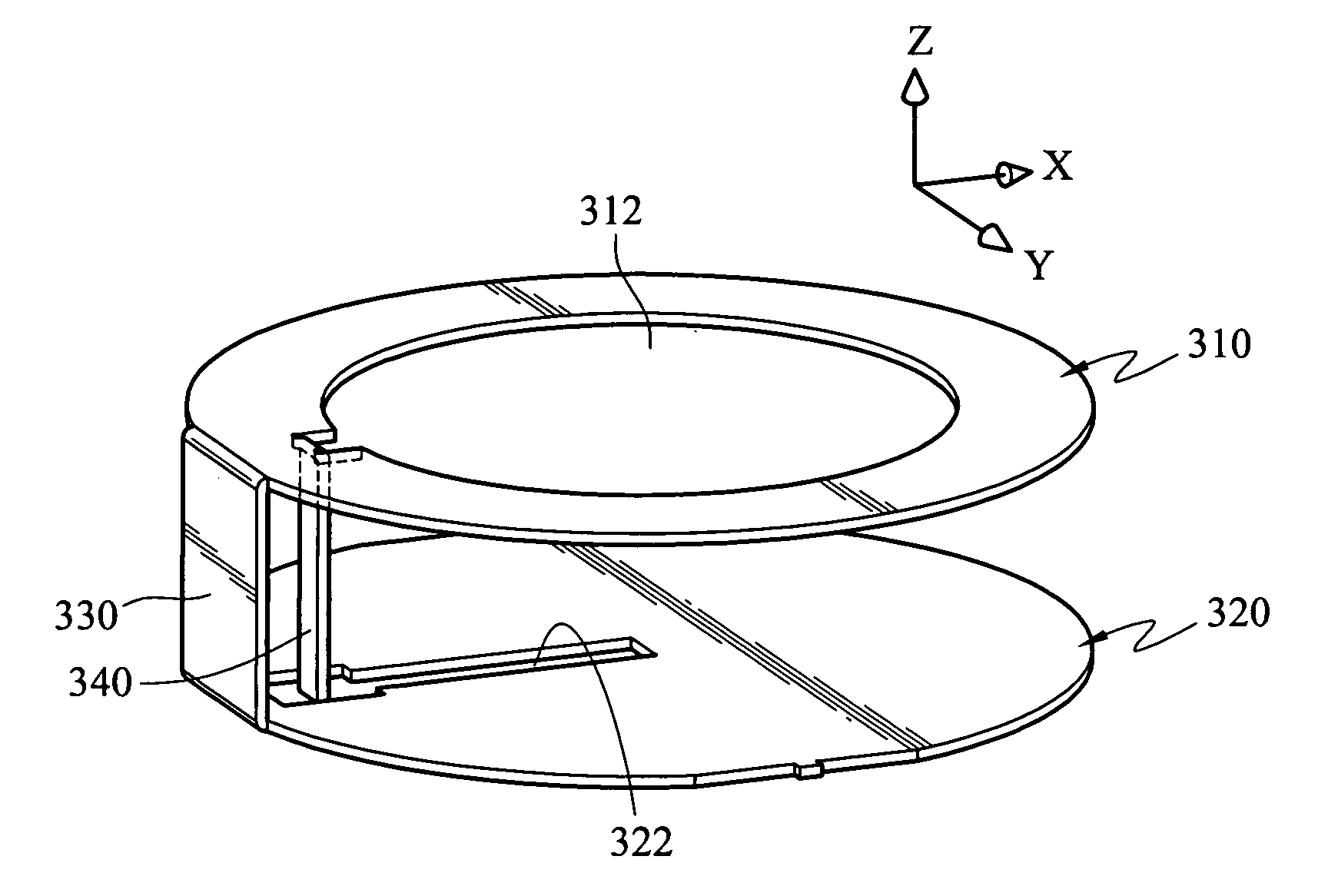
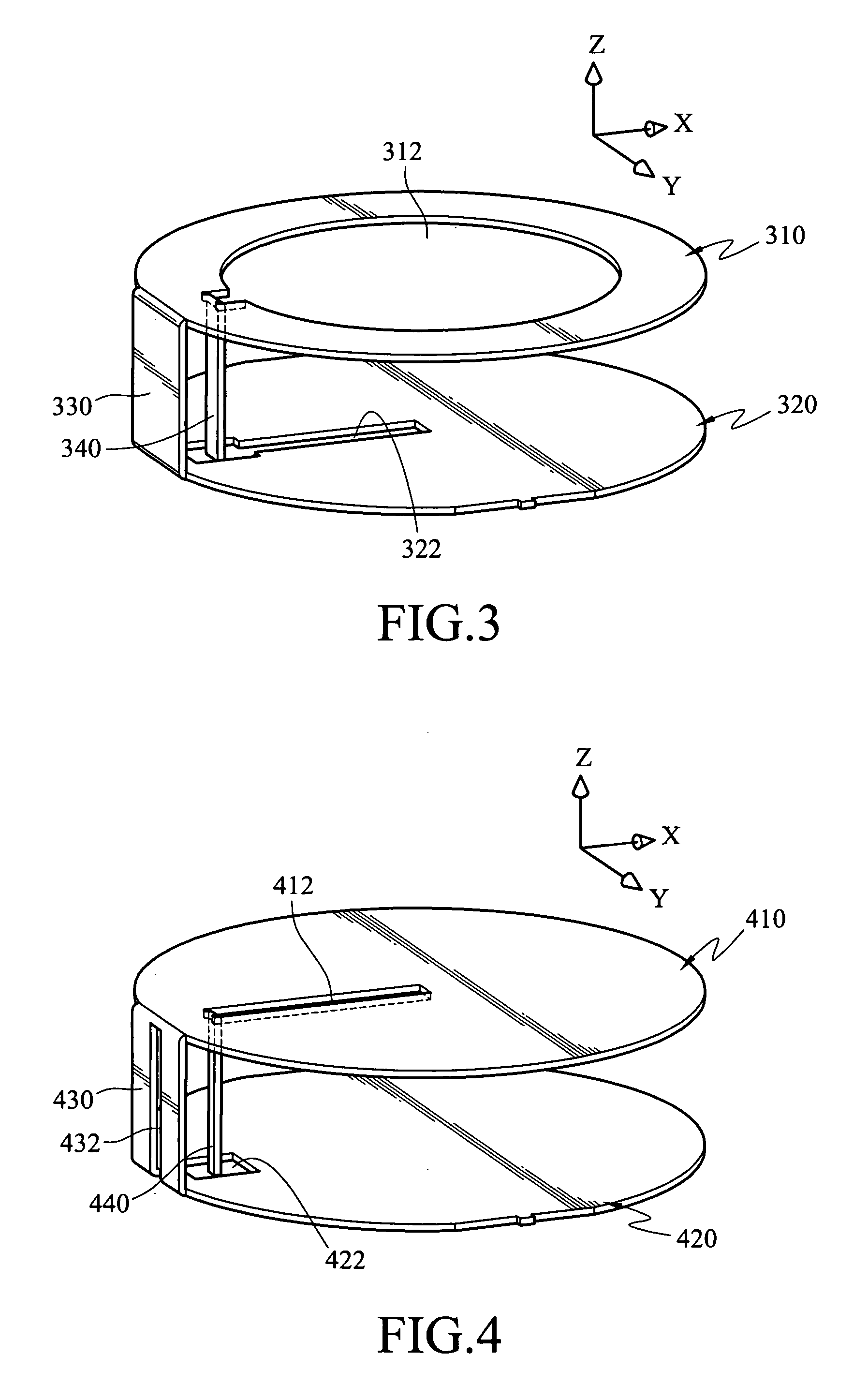
[0051] Refer to FIG. 3 for the planar inverted F antenna (PIFA) of the invention adopted for use on a wireless communication device. It includes a radiation portion 310, a ground portion 320, a short portion 330 and a feed section 340.
[0052] The radiation portion 310 aims to receive or transmit radio signals for the wireless communication device.
[0053] The ground portion 320 is securely mounted onto the wireless communication device by soldering or bonding (through double-sided adhesive tape or Velcro strips).
[0054] The short portion 330 bridges the radiation portion 310 and the ground portion 320, braces the radiation portion 310, and spaces the radiation portion 310 from the ground portion 320 at a small distance. In this embodiment the short portion 330 forms an included angle with the radiation portion 310 and the ground portion 320 of about 90 degrees. Hence the radiation portion 310 is substantially in parallel with the ground portion 320.
[0055] The feed section 340 is loca...
second embodiment
[0063] Refer to FIG. 4 for the PIFA according to the invention, and it includes a radiation portion 410, a ground portion 420 and a short portion 430. As the ones set forth above, the radiation portion 410 has a first opening 412, and the ground portion 420 has a second opening 422. A short portion 430 has a third opening 432 to enable one end of a conductive wire to run through and connect electrically to a feed section 440. The conductive wire has another end connecting electrically to a transmission circuit of a wireless communication device. While the conductive wire is connected electrically to the feed section 440, it must not make contact with the short portion 430, or the conductive wire must be shielded by an insulation layer. The conductive wire may be a coaxial cable. The third opening 432 is a slot or other geometric shape. In this embodiment the third opening 432 divides the short portion 430 into two sections, namely, two thin metal sheets. Each section has one end con...
third embodiment
[0064] Refer to FIG. 5 for the PIFA of the invention. It includes a radiation portion 510, a ground portion 520 and a short portion 530 that are substantially constructed as the ones set forth above, thus details are omitted, wherein the radiation portion 510 has a first opening 512, and the ground portion 520 has a second opening 522. The ground portion 520 has a second opening 522 corresponding to a feed section 540 but which is larger than the feed section 540 to prevent the feed section 540 from coming in contact with the ground portion 520 and creating a short circuit. Moreover, if the feed section 540 is long enough, it can pass through the ground portion 520 without coming into contact therewith. Hence when the ground portion 520 is coupled on a circuit board of a wireless communication device, the feed section 540 is connected electrically to the transmission circuit of the wireless communication device.
[0065] In addition, a passing through portion 542 of the feed section 54...
PUM
 Abstract
Description
Claims
Application Information