
Brightness level converting apparatus, brightness level converting method, solid-state image pickup apparatus, brightness level converting program, and recording medium

a technology of brightness level and converting method, which is applied in the field of brightness level converting method, solid-state image pickup apparatus, brightness level converting program, and recording medium, can solve the problems of difficult to find out what subject is displayed by the image displaying apparatus, image obtained is entirely unnatural, and image with low contrast is displayed. to achieve the effect of improving the contrast of an imag

Inactive Publication Date: 2006-07-27
SHARP KK
View PDF14 Cites 43 Cited by
  • Summary
  • Abstract
  • Description
  • Claims
  • Application Information

AI Technical Summary

Benefits of technology

[0025] The present invention was made to solve the problem above, and an object of the present invention is to provide (I) a brightness level converting apparatus that improves the contrast of an image represented by an image pickup signal supplied from a logarithmic conversion solid-state image pickup device so as to produce a natural-looking image, (II) a brightness level converting method, (III) a solid-stare image pickup apparatus, (IV) a brightness level converting program, and (V) a recording medium.
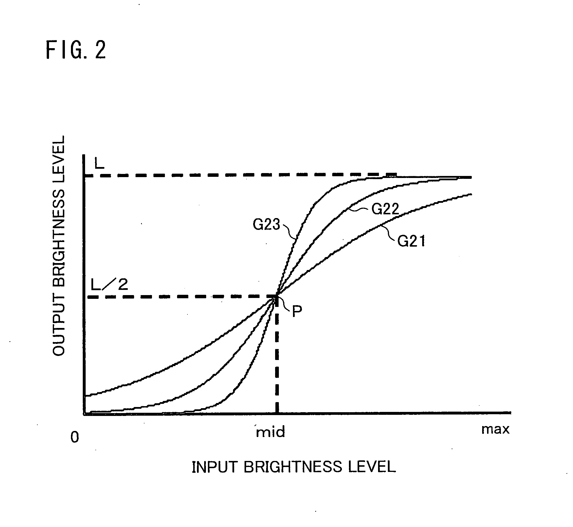
[0029] In this manner, using the above-described brightness level converting function, the brightness level converting means reduces the contrast of the image pickup signal, except in the input brightness levels around the inflexion point of the brightness level converting function. At the same time, the brightness level converting means significantly improves the contrast in the input brightness levels around the inflexion point of the brightness level converting function. On this account, an image represented by the image pickup signal after being subjected to the brightness level conversion looks natural, as compared to a case where a partial brightness level region of the image pickup signal is cut out and a gradation indicating the degree of changes in the brightness levels of the partial brightness level region is linearly increased.
[0033] According to the arrangement above, it is possible to obtain a solid-state image pickup apparatus that can improve the contrast of an image represented by an image pickup signal supplied from a logarithmic conversion solid-state image pickup device, so as to produce a natural-looking image.

Problems solved by technology

However, a problem explained below arises when the image displaying apparatus displays such image or video without modification.
In such image or video, it may be difficult to find out what subject is displayed by the image displaying apparatus.
Therefore, if, when performing an image display based on an output image pickup signal from the solid-state image pickup device, the entire output dynamic range of the solid-state image pickup device is so set as to be within the dynamic range of the image displaying apparatus, there occurs a problem in that the image with low contrast is displayed.
When the image displaying apparatus displays the image represented by such image pickup signal, the following problem arises.
Therefore, in the case of converting the brightness levels in the image pickup signal by using the conventional method disclosed in the above-described Document, the image obtained is entirely unnatural, gives poor impression, and has a blurred contrast as compared with the case of converting the brightness levels in the image pickup signal by using a curve G122 that is a straight line indicating the relation between the incident light quantity and the brightness level.
In such a case, if the brightness levels are converted by using the conventional method described above, human or machines may make a wrong judgment on the basis of the image whose gradation property deteriorates after converting the brightness levels.
On this account, there may be a possibility that a serious trouble or accident occurs.
A similar problem occurs in an example shown in FIG. 27. FIG. 27 is a histogram showing the relation, between the brightness level and the number of pixels in the image pickup signal, in the image obtained by imaging a dark subject and a bright subject together by the logarithmic conversion solid-state image pickup device.
Therefore, the contrast is not enough in both the dark portion and the bright portion in the image displayed.
Again, human or machines may make a wrong judgment on the basis of the image whose gradation deteriorates after converting the brightness levels.
On this account, there may be a possibility that a serious trouble or accident occurs.

Method used


Image

  • Brightness level converting apparatus, brightness level converting method, solid-state image pickup apparatus, brightness level converting program, and recording medium
  • Brightness level converting apparatus, brightness level converting method, solid-state image pickup apparatus, brightness level converting program, and recording medium
  • Brightness level converting apparatus, brightness level converting method, solid-state image pickup apparatus, brightness level converting program, and recording medium

Examples


embodiment 1

[0068] Referring to FIGS. 1 to 10, the following will explain Embodiment 1 of the present invention.

[0069] (Brief Overview of Solid-State Image Pickup Apparatus 1)

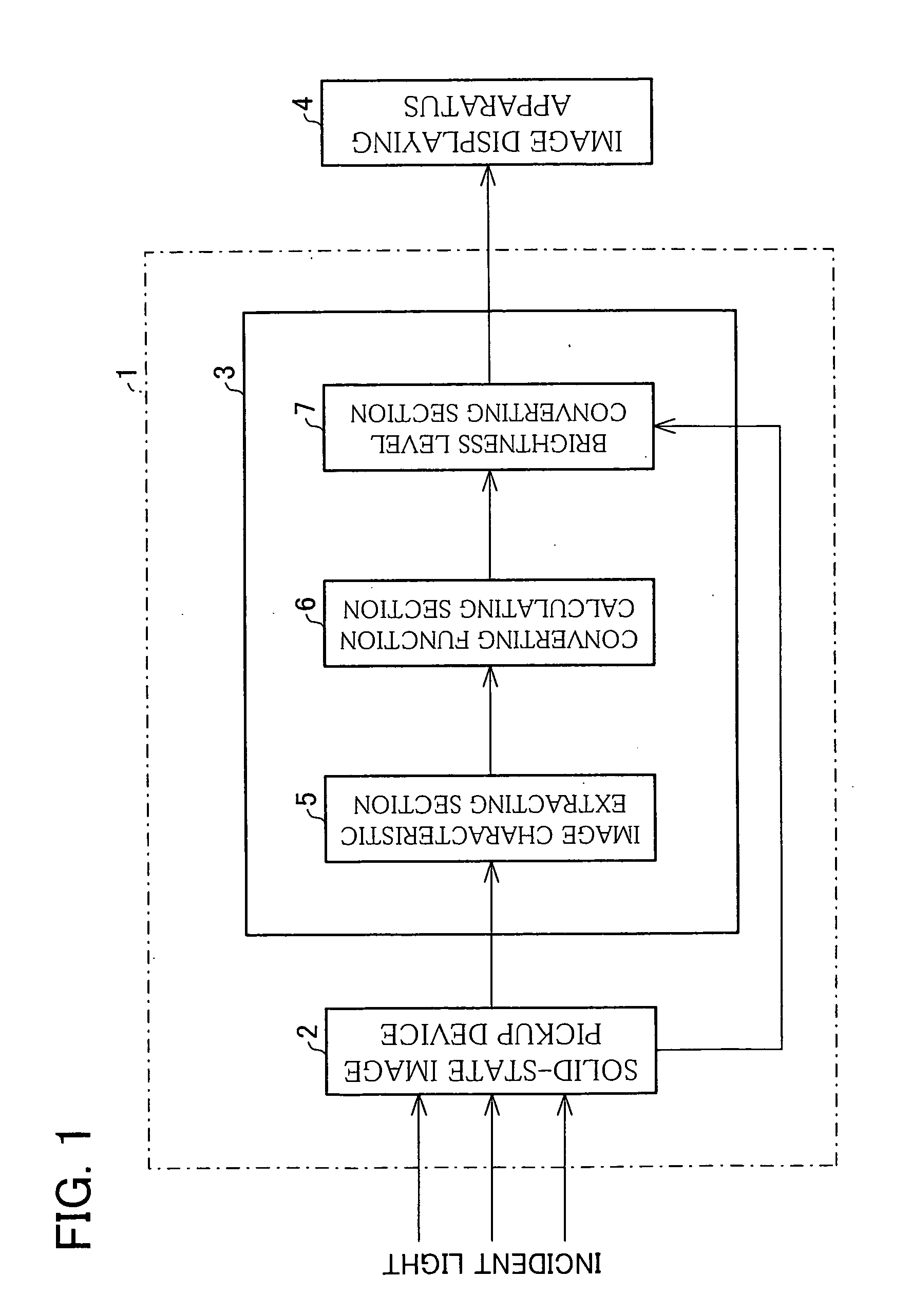
[0070]FIG. 1 is a block diagram showing details of a solid-state image pickup apparatus 1 of the present invention. As shown in FIG. 1, the solid-state image pickup apparatus 1 includes a solid-state image pickup device 2 and a brightness level converting apparatus 3. The solid-state image pickup device 2 is a logarithmic conversion solid-state image pickup device, and it picks up a subject. Specifically, the solid-state image pickup device 2 logarithmically converts the quantity of light into a brightness level. Note that the light is emitted from the subject or reflected by the subject, and then the light is incident on a surface of the solid-state image pickup device 2 through an optical system, such as a lens. Thus, the solid-state image pickup device 2 generated an image pickup signal expressing an image of the subj...

embodiment 2

[0153] Referring to FIGS. 13 to 20, the following will explain Embodiment 2 of the present invention.

[0154] A solid-state image pickup apparatus 1 of the present embodiment is schematically shown in FIG. 1, which is a block diagram of the solid-state image pickup apparatus 1. Because the solid-state image pickup apparatus 1 in the present embodiment is similar to that in Embodiment 1, the detailed explanation of the configuration of the solid-state image pickup apparatus 1 is omitted here. In the present embodiment, the brightness level converting apparatus 3 is different from that in Embodiment 1 in terms of its configuration and operation. The following will explain in detail the configuration and operation of the brightness level converting apparatus 3.

[0155] The brightness level converting apparatus 3 converts the brightness levels in the image pickup signal output thereto from a solid-state image pickup device 2. As shown in FIG. 1, the brightness level converting apparatus 3...

embodiment 3

[0236] Referring to FIGS. 22 to 24(b), the following will explain Embodiment 3 of the present invention.

[0237] The general block configuration of a solid-state image pickup apparatus 1 of the present embodiment is identical with the solid-state image pickup apparatuses 1 of Embodiments 1 and 2. Detailed description of the apparatus 1 of the present embodiment is therefore not given.

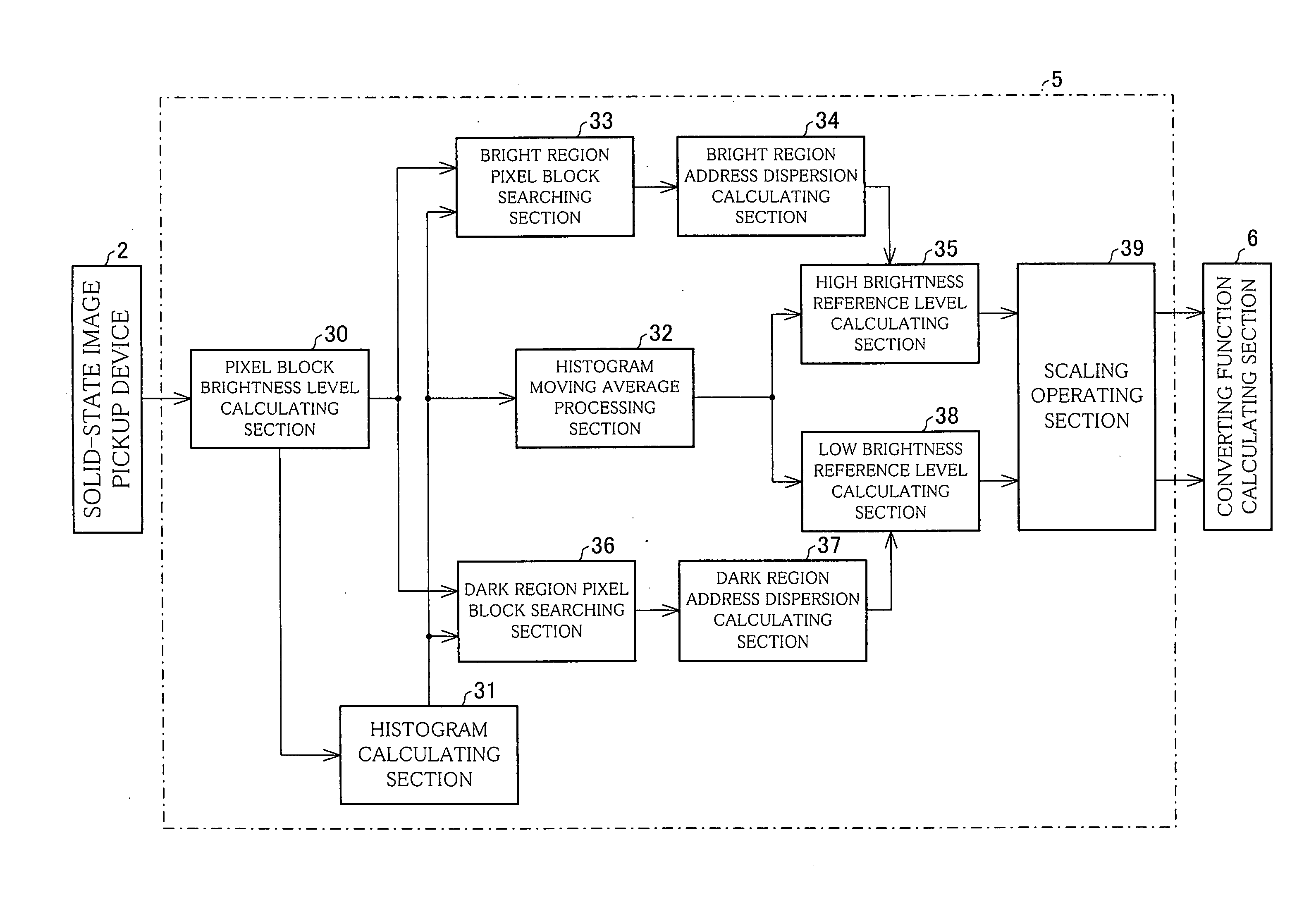
[0238] A brightness level converting apparatus 3 converts the brightness level in an image pickup signal output from a solid-state image pickup device 2. As shown in FIG. 1, the brightness level converting apparatus 3 includes the image characteristic extracting section 5, the converting function calculating section 6 (function calculating means), and the brightness level converting section 7 (brightness level converting means).

[0239] The image characteristic extracting section 5 extracts the characteristic of an image which is picked up by the solid-state image pickup device 2. More specifically, on t...


PUM


Abstract

A brightness level converting apparatus improves a contrast of an image represented by an image pickup signal output from a logarithmic conversion solid-state image pickup device, so as to obtain a natural image. For this purpose, the brightness level converting apparatus converts brightness levels in the image pickup signal output from the solid-state image pickup device which logarithmically converts an incident light quantity. In the brightness level converting apparatus, a brightness level converting section converts the brightness levels in the image pickup signal by using a brightness level converting function expressed by an S-shaped curve which indicates the relation between an input brightness level and an output brightness level and includes one inflexion point. Therefore, the contrast in a low brightness level range in the image pickup signal is reduced. At the same time, the contrast in a high brightness level range is reduced while appropriately keeping a gradation. With this, the contrast in an intermediate brightness level range in the image pickup signal is improved considerably. Therefore, the image represented by the image pickup signal whose brightness levels are converted becomes a further natural image.

Description

[0001] This Nonprovisional application claims priority under 35 U.S.C. § 119(a) on Patent Application Nos. 017425 / 2005 and 358269 / 2005 filed in Japan respectively on Jan. 25, 2005, and Dec. 12, 2005, the entire contents of which are hereby incorporated by reference. FIELD OF THE INVENTION [0002] The present invention relates to (I) a brightness level converting apparatus for converting brightness levels in an image pickup signal output from a logarithmic conversion solid-state image pickup device, (II) a method for converting the brightness levels, (III) a solid-state image pickup apparatus, (IV) a program for converting the brightness levels, and (V) a recording medium. BACKGROUND OF THE INVENTION [0003] Presently, photographic devices, such as digital still cameras and movie cameras, are widely prevalent. Such photographic device usually includes a CCD (Charge Coupled Device) as a solid-state image pickup device for imaging a subject. In the CCD, a dynamic range for incident light...

Claims


Application Information

Patent Timeline
IPC IPC(8): H04N9/68H04N5/243
CPCG06T5/009G06T5/40G06T2207/20021H04N5/20H04N5/202H04N5/243H04N23/76G06T5/92A01K61/73A01K61/51E02B3/046E02B3/043
Inventor SHIBANO, TOSHINOBUHASHIGUCHI, KAZUO
Owner SHARP KK
Learn More