Image Processing Apparatus, Information Processing Apparatus, Information Processing System, Information Processing Method, and Storage Medium

a technology of image processing apparatus and user interface, applied in the field of user interface customization technique of image processing apparatus, can solve the problem that all image processing apparatuses increase the burden on the administrator of those apparatuses, and achieve the effect of easy customization

Inactive Publication Date: 2006-07-27
CANON KK
View PDF12 Cites 20 Cited by
  • Summary
  • Abstract
  • Description
  • Claims
  • Application Information

AI Technical Summary

Benefits of technology

[0015] According to the present invention, in a system with a plurality of image processing apparatuses connected to enable t

Problems solved by technology

However, in, e.g., a company which has introduced a number of image processing apparatuses, customiz

Method used


Image

  • Image Processing Apparatus, Information Processing Apparatus, Information Processing System, Information Processing Method, and Storage Medium
  • Image Processing Apparatus, Information Processing Apparatus, Information Processing System, Information Processing Method, and Storage Medium
  • Image Processing Apparatus, Information Processing Apparatus, Information Processing System, Information Processing Method, and Storage Medium

Examples


first embodiment

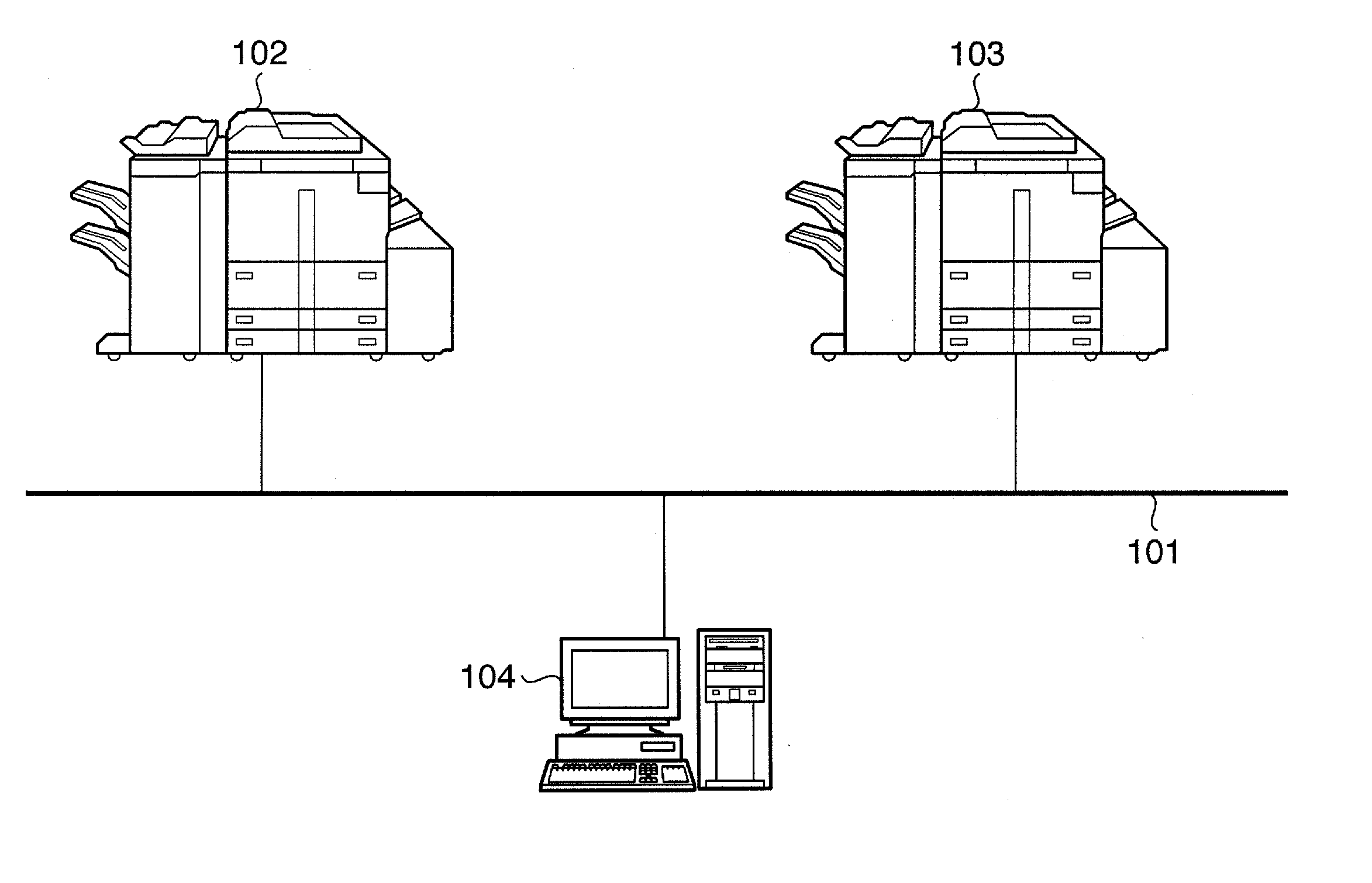
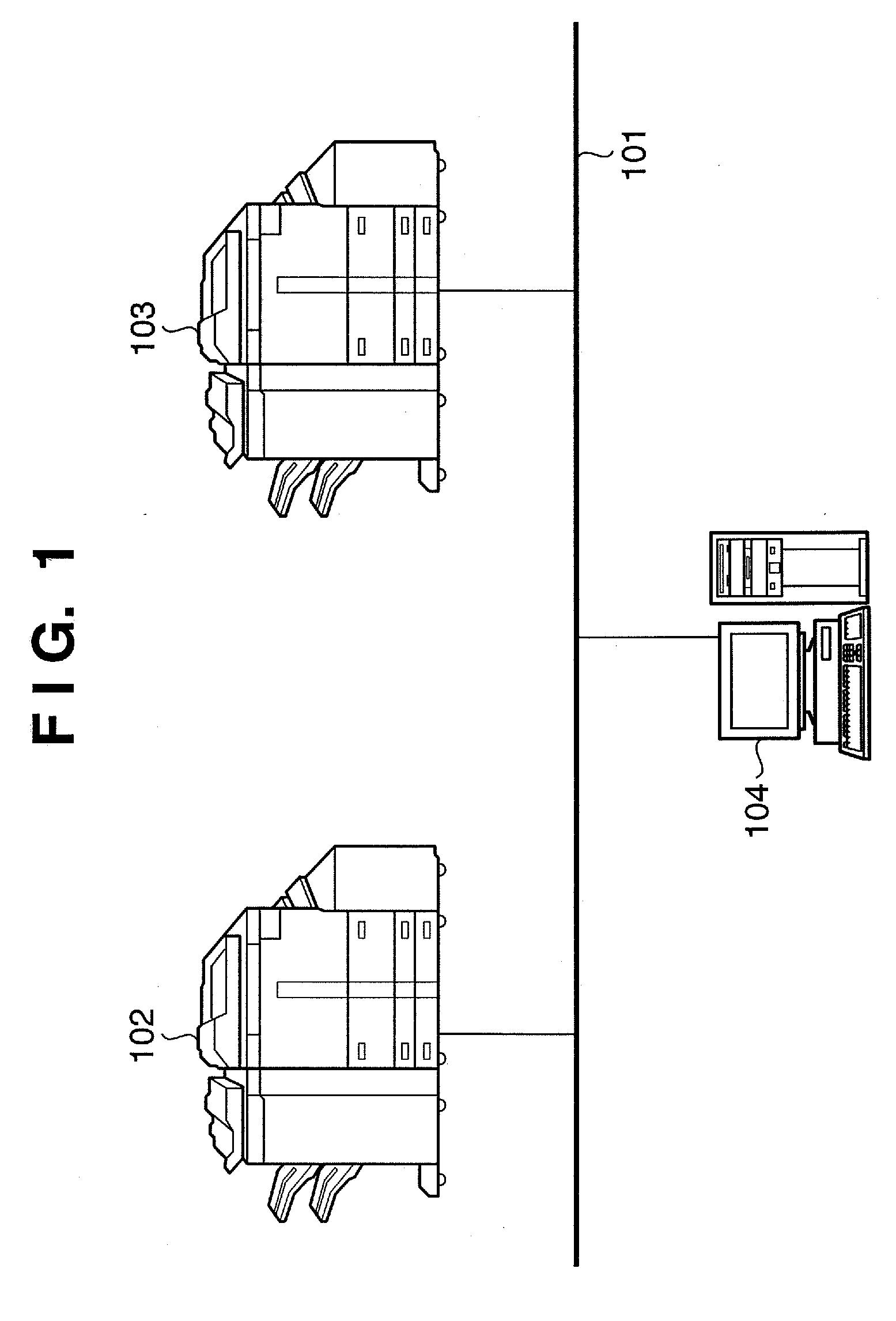
[0032]FIG. 1 is a view showing the configuration of an information processing system according to an embodiment of the present invention in which a plurality of copying machines are connected communicably.

[0033] Referring to FIG. 1, reference numeral 101 denotes a LAN; 102 and 103, copying machines; and 104, a GUI generation device (more specifically, a personal computer (PC) having a GUI generation function). With this arrangement, the copying machines 102 and 103 can display, on their operation panels, a screen acquired from the GUI generation device.

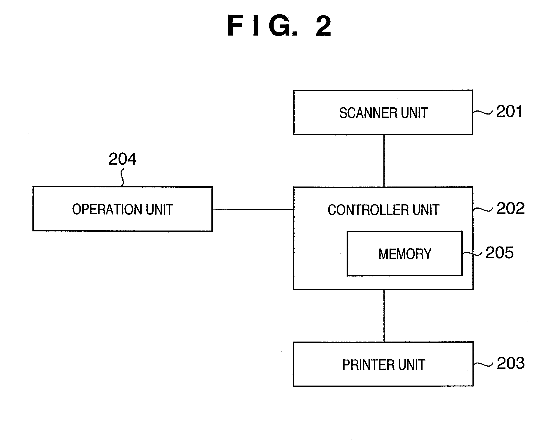
[0034] The functional arrangement of the copying machine (102, 103) according to the embodiment of the present invention will be described next with reference to FIG. 2.

[0035]FIG. 2 is a block diagram showing the functional arrangement of the copying machine. The block diagram particularly illustrates a digital multifunction apparatus with COPY, PRINT, and FAX functions.

[0036] Referring to FIG. 2, a scanner unit 201 reads a docume...

second embodiment

[0074] In the first embodiment, a screen information request is sent to the GUI generation device every time a screen is to be generated. However, the present invention is not particularly limited to this. For example, a GUI generation device (104) may be configured to be selectively usable considering reduction of the processing load on the GUI generation device and disconnection of the network.

[0075]FIG. 10 is a flowchart showing the flow of customization processing when the GUI generation device is configured to be selectively usable in image generation.

[0076] At the start of new screen display, in step S1001, it is determined whether screen customization is necessary. The necessity of customization may be determined on the basis of, e.g., information which is held in the copying machine in advance and represents whether customized screen information is registered in the GUI generation device 104. Determination may be done on the basis of an inquiry result obtained by inquiring...

third embodiment

[0082] The first and second embodiments contain no mention of the application to request screen information of the GUI generation device and display screen information received from the GUI generation device. A Web browser may be used as the application.

[0083] The screen information request may be sent not to a PC with the GUI generation function but to, e.g., a database server which holds screen information as a database. This embodiment will be described below.

[0084]FIG. 11 is a block diagram showing the functional arrangement of a copying machine and the functional arrangement of a database server according to the second embodiment of the present invention. A copying machine 1101 and database server 1110 are connected communicably through a network 1120.

[0085] As shown in FIG. 11, the copying machine 1101 comprises a network connection unit 1102, Web browser 1103, display unit 1104, corresponding address database 1105, controller unit 1106, key input unit 1107, scanner unit 11...


PUM


Abstract

In a system with a plurality of image processing apparatuses connected communicably, customization of various kinds of information displayed on each image processing apparatus is facilitated. In order to achieve this object, an information processing method of the invention is an information processing method in a copying machine (102) communicably connected to a GUI generation device (104). The method includes a display step of displaying a screen registered in advance in image processing, a step (step S601) of requesting, of the GUI generation device (104), information about the display contents of the screen in a predetermined state, a step (step S602) of receiving the information about the display contents of the screen from the GUI generation device (104), and a step of generating a screen by using the received information about the display contents of the screen. In the display step, the screen generated in the generation step is displayed in the predetermined state.

Description

FIELD OF THE INVENTION [0001] The present invention relates to a user interface customization technique in an image processing apparatus. BACKGROUND OF THE INVENTION [0002] In an image processing apparatus such as a copying machine or facsimile apparatus, conventionally, various kinds of information are displayed on an operation panel provided on the apparatus main body to inform a user of various kinds of information set as processing conditions for image processing or information about the internal state of the apparatus. [0003] To ensure better operability for the user or to allow the apparatus administrator to limit functions available to the user, various kinds of information to be displayed can be customized in the apparatus. [0004] However, in, e.g., a company which has introduced a number of image processing apparatuses, customizing all image processing apparatuses increases the burden on the administrator of those apparatuses. [0005] For this reason, in a system having a pl...

Claims


Application Information

Patent Timeline
IPC IPC(8): G06F3/12
CPCH04N1/00127H04N1/00344H04N1/00408H04N1/0097H04N1/32657H04N2201/001H04N2201/0039H04N2201/0094
Inventor YAMADA, TETSUYAKUROYANAGI, SATOSHI
Owner CANON KK
Why Eureka
Try Eureka