Capacitively coupled power supply

a power supply and capacitive technology, applied in the field of capacitive coupling power supply, can solve the problems of disadvantage, excessive current in the primary winding, bulky and expensive devices, and large transformers in siz

Active Publication Date: 2006-07-27
INTERDIGITAL MADISON PATENT HLDG
View PDF2 Cites 27 Cited by
  • Summary
  • Abstract
  • Description
  • Claims
  • Application Information

AI Technical Summary

Problems solved by technology

In the event of a overloading, the current in the primary winding might be, disadvantageously, excessive and may damage, for example, a power transistor that drives the transformer.
Additionally, transformers are typically large in size (due to the size of the magnetic elements within them), bulky and expensive devices.

Method used


Image

  • Capacitively coupled power supply
  • Capacitively coupled power supply
  • Capacitively coupled power supply

Examples


Embodiment Construction

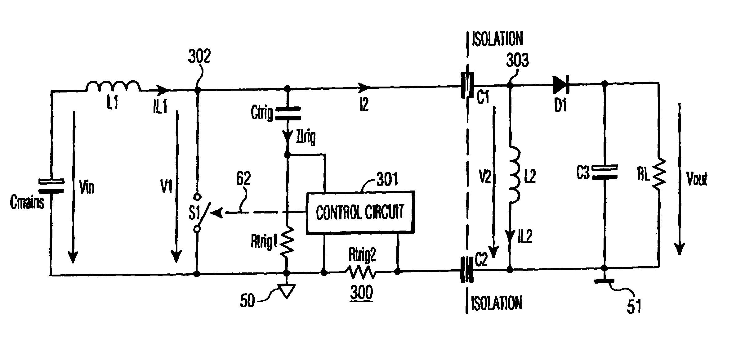
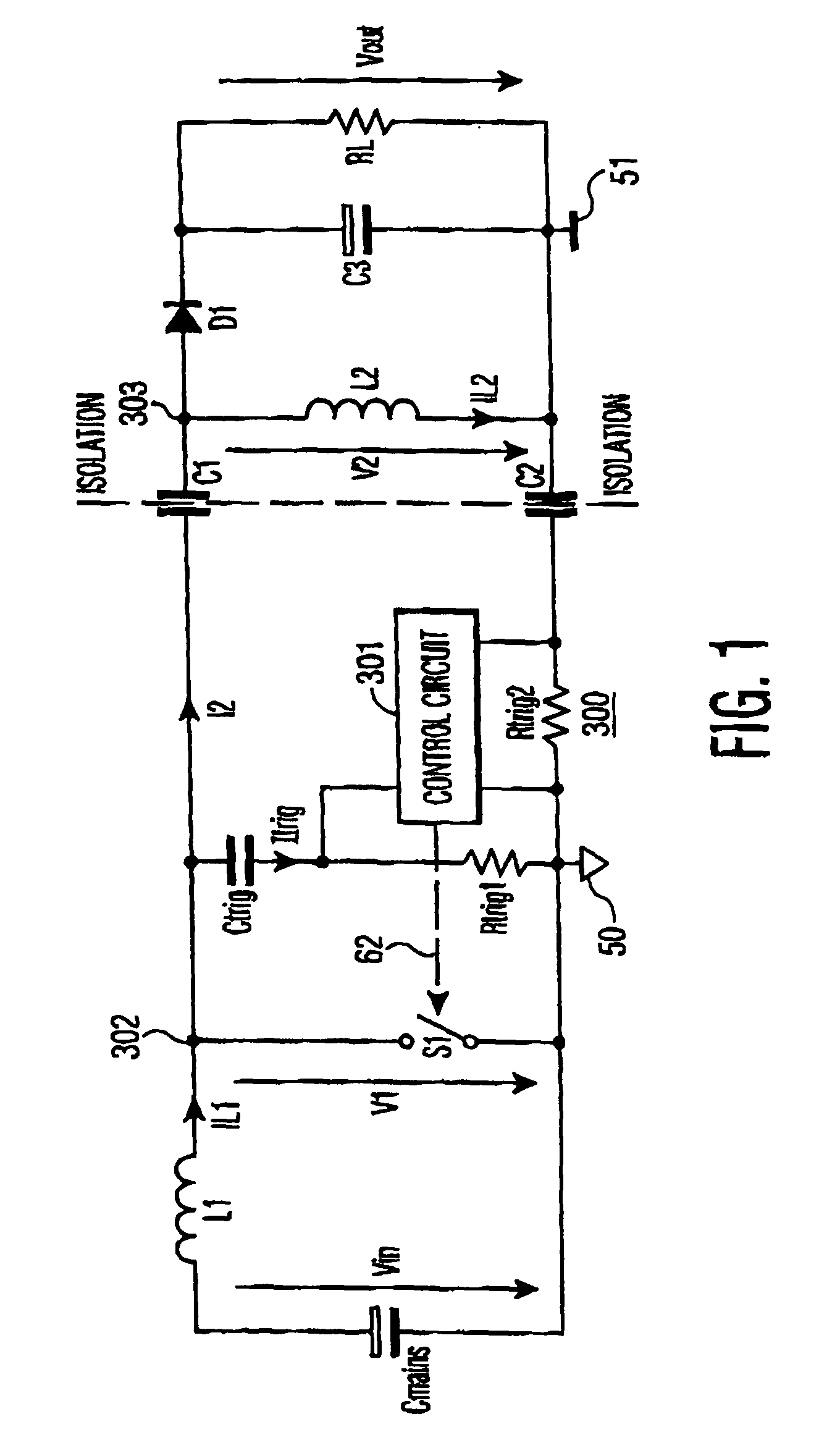
[0014]FIG. 1 illustrates a power supply 300, partially in a schematic form, with capacitive mains isolation, embodying an inventive feature. An input supply voltage Vin referenced to a “hot” ground conductor 50 is produced in, for example, a conventional bridge rectifier, not shown, and is non-isolated from “hot” ground conductor 50. Voltage Vin is coupled via a supply inductor L1 to a terminal 302 of a switch S1 formed by a switching power transistor, not shown, that is controlled by a control circuit 301 to switch a high frequency. Terminal 302 is coupled to ground conductor 50 when switch S1 is conductive.

[0015] When switch S1 is non-conductive, terminal 302 is coupled to ground conductor 50 via a series arrangement of a first isolation capacitor C1, a second isolation capacitor C2, a second supply inductor L2 that is coupled between capacitors C1 and C2 and a current sampling resistor Rtrig2. Current sampling resistor Rtrig2 is coupled between capacitor C2 and ground conductor ...


PUM


Abstract

A power supply includes a supply inductor and a first capacitor coupled to form a resonant circuit to generate a resonant waveform in a resonant operation, during a first portion of an operation cycle of the power supply. A charge storage element develops an output voltage to energize a load. A rectifier is coupled to the charge storage element and to the resonant circuit and is responsive to the resonant waveform for applying the output voltage back to the resonant circuit to interrupt the resonant operation, at an end time of the operation cycle first portion, when the resonant waveform produces a first change of state in the rectifier. A first sensor senses when the first change of state in the rectifier occurs. A source of a supply current is coupled to the rectifier and rectified in the rectifier to produce a rectified current that is coupled to the charge storage element to replenish a charge therein, during a second portion of the operation cycle. A switching transistor is responsive to an output signal of the first sensor for enabling the supply current to be coupled to the rectifier, during the operation cycle second portion, and for disabling the supply current from being coupled to the rectifier, during the operation cycle first portion.

Description

RELATED APPLICATIONS [0001] The present application claims priority under 35 U.S.C. § 119 of Provisional Patent Application Ser. No. 60 / 418,823 filed on Oct. 16, 2002.FIELD OF THE INVENTION [0002] The present invention relates to power supplies in general, and more particularly, to generating a supply voltage using capacitive coupling in a main current path. BACKGROUND OF THE INVENTION [0003] Power supplies serve the purpose of converting an input voltage into one or several output voltages. An AC power source may be used to provide an AC power line input, which gets converted to a DC regulated output voltage. Transformers are typically used to provide isolation between a “hot” ground and a “cold” ground for a power supply or a converter. A primary winding of a transformer typically conducts a non-isolated direct current (DC). In the event of a overloading, the current in the primary winding might be, disadvantageously, excessive and may damage, for example, a power transistor that ...

Claims


Application Information

Patent Timeline
Patent Type & Authority Applications(United States)
IPC IPC(8): H02M3/335H02M3/00H02M3/155H02M3/156
CPCH02M1/32H02M3/005H02M3/156Y02B70/1425Y02B70/10H02M7/06
Inventor WEBER, RUDOLF
Owner INTERDIGITAL MADISON PATENT HLDG
Why Eureka
Try Eureka