
Architecture of an onboard aircraft piloting aid system

a technology for aircraft and pilots, applied in process and machine control, instruments, navigation instruments, etc., can solve the problems of insufficient architecture of the system with a single gnss subsystem to satisfy integrity and continuity, board cpu/sub>3/sub>has a characteristic failure rate that is far too high

Active Publication Date: 2006-07-27
THALES SA
View PDF14 Cites 34 Cited by
  • Summary
  • Abstract
  • Description
  • Claims
  • Application Information

AI Technical Summary

Benefits of technology

The invention proposes a less expensive navigation system for precision approach operations in aviation. It uses existing equipment and distributes the various functions needed for accurate guidance in all weather conditions. The system includes an inertial reference system, a multimode receiver with integrated GNSS and augmentation systems, and a single augmented GNSS signal processing board. The system also includes a function for generating guidance data from the GNSS data and inertial data, as well as a function for checking the guidance data with the inertial data. The invention provides a reliable and affordable solution for precision approach operations, regardless of the weather conditions, and can be used anywhere in the world.

Problems solved by technology

In practice, a digital processing board can normally guarantee at best only 10−6 errors per hour of flight greater than the error risk tolerated for the application, this risk typically being evaluated at 10−9 errors per hour of flight.
As for the ILS radiofrequency or MLS signal reception subsystem, the analogue / digital boards A / D for receiving corresponding radiofrequency signals normally present failure rates well below the error risk tolerated for the application, the risk being typically estimated at 10−9 errors per hour of flight.
It will be understood that the architecture of the system with a single GNSS subsystem is insufficient to satisfy the integrity and continuity imperatives of the application in category III mode.
In particular, the board CPU3 has a characteristic failure rate that is far too high.
Such a solution therefore entails reviewing the current architecture of the onboard multimode receivers, resulting in a high development cost for the definition, debugging and certification of this new architecture.
Furthermore, the GNSS-IRS data hybridation aspects add new fault detection constraints, such that duplicating the GNSS subsystem might not be enough to resolve the problem adequately, resulting in a more complete revision of the very system architecture.

Method used


Image

  • Architecture of an onboard aircraft piloting aid system
  • Architecture of an onboard aircraft piloting aid system
  • Architecture of an onboard aircraft piloting aid system

Examples


Embodiment Construction

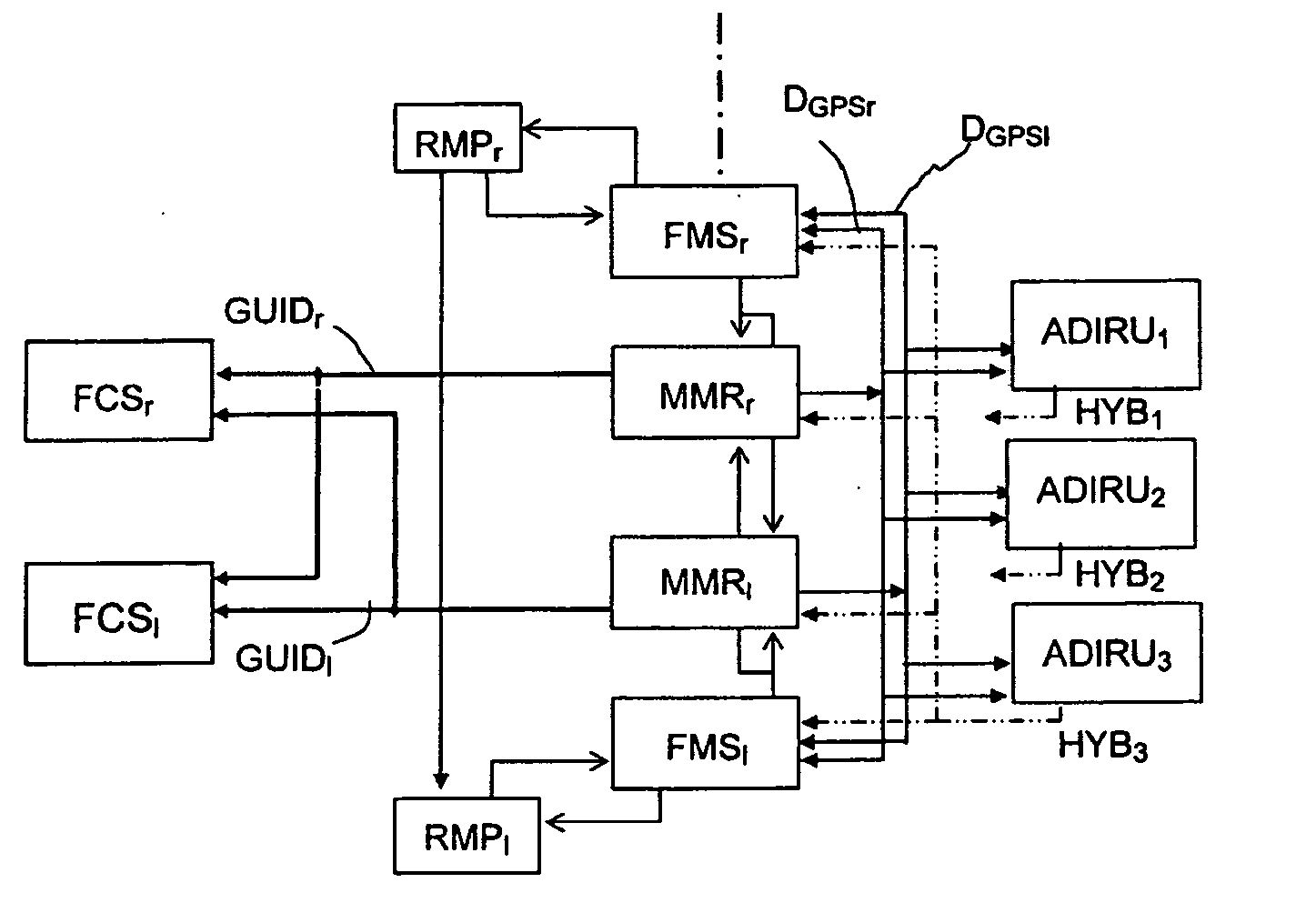
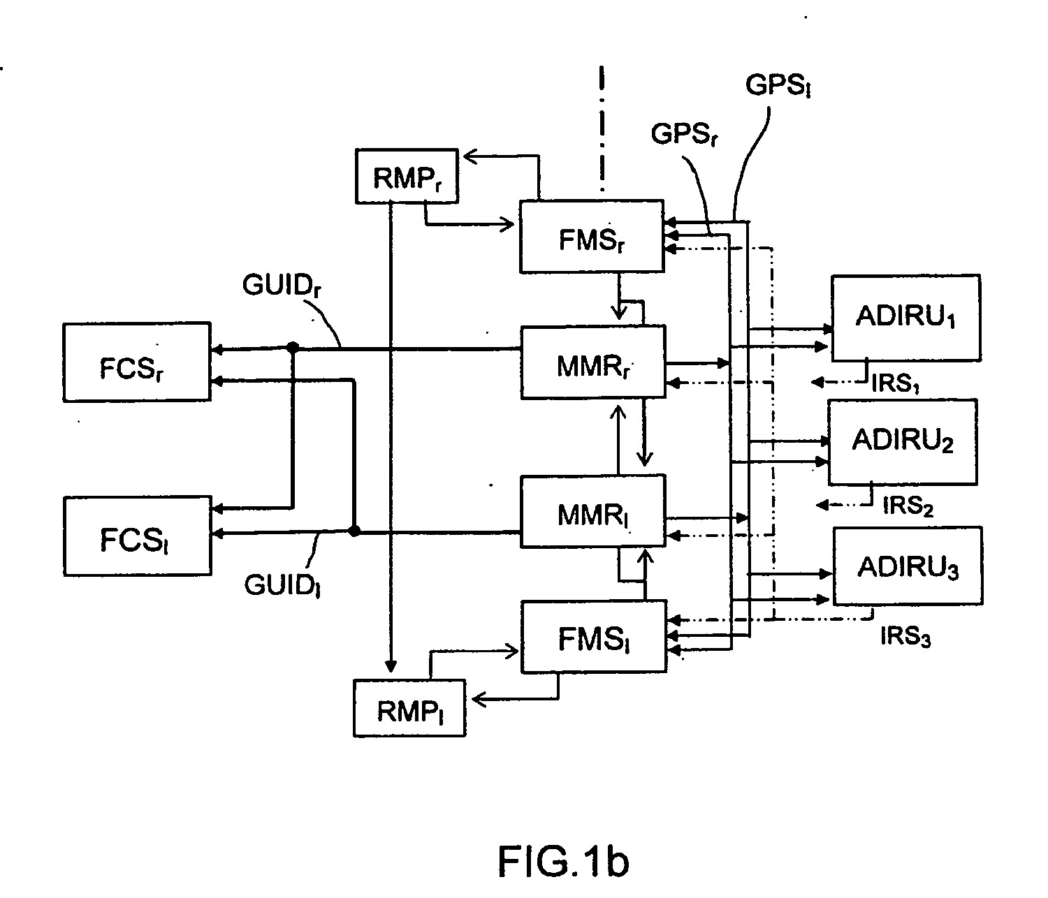
[0066] In the description below, and with reference to the figures, the following notations are used: [0067] DGPSr, DGPSl designate the data obtained from the GNSS signals SGPS and augmentation signals Saug, typically the GBAS augmentation signals, or even the SBAS augmentation signals. This data is supplied as output from the receivers MMRr, MMRl respectively. [0068] IRSi designates the inertial data supplied by the inertial reference ADIRUi unit i of the IRS system over an associated input / output bus.

[0069] HYBi designates the hybrid data between the data DGPSr and / or DGPSl and the inertial data from the unit ADIRUi of the inertial reference system.

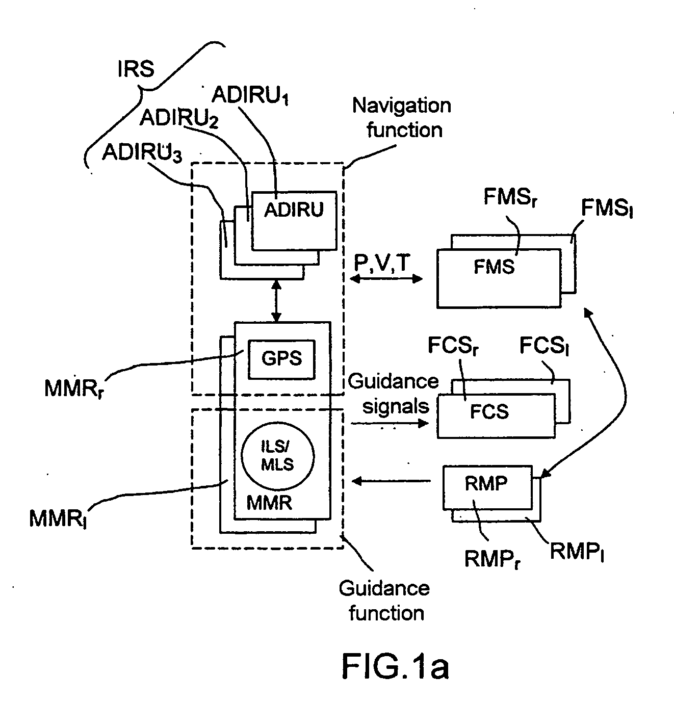
[0070] A distribution according to the invention of the functions of the GLS processing subsystem is based on the existing redundant structures of the navigation system as previously described and illustrated in FIGS. 1a, 1b and 2. In particular, this distribution relies on the links provided between the various elements, in particula...


PUM


Abstract

A function for generating guidance data from the GNSS data and the inertial data (IRS1) with integrated fault detection is distributed on the inertial reference units and the digital processing boards of said multimode receivers. Application to an augmented GLS guidance mode for category I to III approach operations.

Description

FIELD OF THE INVENTION [0001] The present invention relates to an aircraft piloting aid system, used in particular to guide the aircraft in precision approach phases (landing, take-off) and manoeuvres on the ground. The invention relates more particularly to the implementation of a GNSS based landing system GLS based on a GNSS satellite positioning system, which satisfies the requirements of guidance signal integrity and continuity for category I to III approaches. [0002] It will be remembered that the integrity represents the probability that the signals are not randomly errored and the continuity represents the probability that the signals remain present and usable during the approach phase. The integrity level is defined in practice for it to be extremely improbable for the surface control system (automatic pilot) which controls the control surfaces of the aeroplane to use false guidance data. The continuity level is defined in practice for it to be extremely improbable for this ...

Claims


Application Information

Patent Timeline
Patent Type & Authority Applications(United States)
IPC IPC(8): G01C21/28G01S19/48
CPCG01C21/165G05D1/0077
Inventor ARETHENS, JEAN-PIERRE
Owner THALES SA
Learn More