Self-Purging Pilot Fuel Injection System

Inactive Publication Date: 2006-08-03
ANSALDO ENERGIA IP UK LTD
View PDF7 Cites 40 Cited by
  • Summary
  • Abstract
  • Description
  • Claims
  • Application Information

AI Technical Summary

Benefits of technology

[0008] In an alternate embodiment, the self-purging pilot fuel injection system further comprises a plurality of second fuel injection orifices that are located proximate the radial inflow swirler and provide a second source of fuel injection. Fuel from the plurality of second

Problems solved by technology

As a result, molecules of fuel remain unburned and result in higher level of emissions.
Should there be a leak in a fuel line,

Method used


Image

  • Self-Purging Pilot Fuel Injection System
  • Self-Purging Pilot Fuel Injection System
  • Self-Purging Pilot Fuel Injection System

Examples


Embodiment Construction

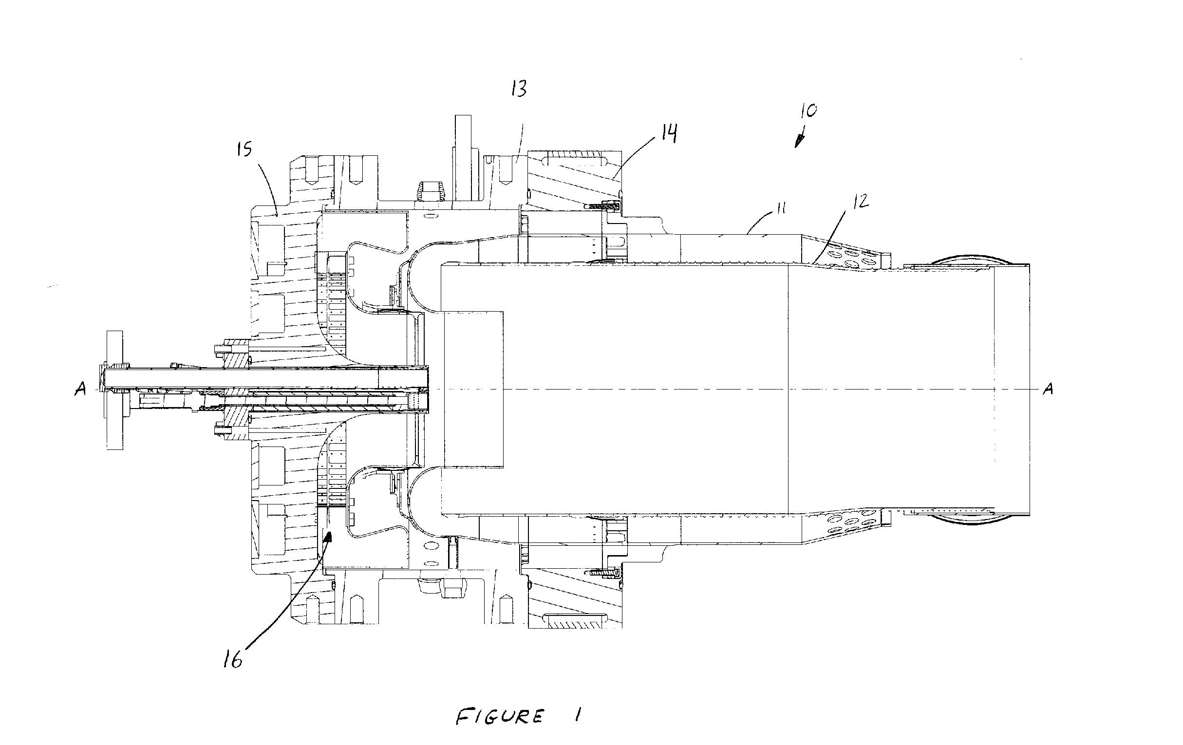
[0014] The preferred embodiment of the present invention will now be described with reference to FIGS. 1-4. A gas turbine combustor 10 incorporating the present invention is shown in cross section in FIG. 1. Combustor 10 comprises a number of components including a flow sleeve 11, combustion liner 12, case 13, main injector 14, end plate 15, and pilot fuel injection system 16. The focus of the present invention is on pilot fuel injection system 16 and its self-purging capability.

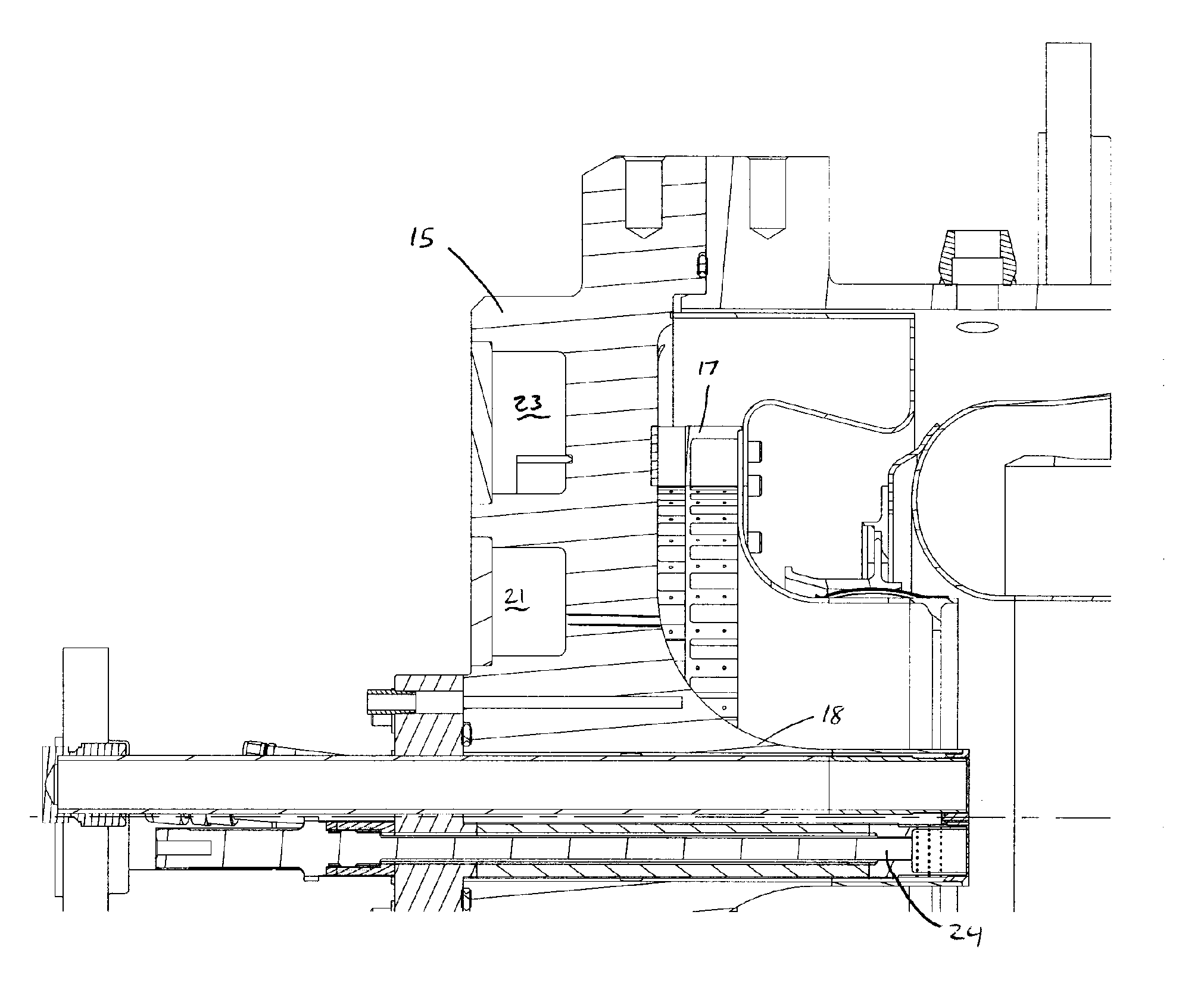
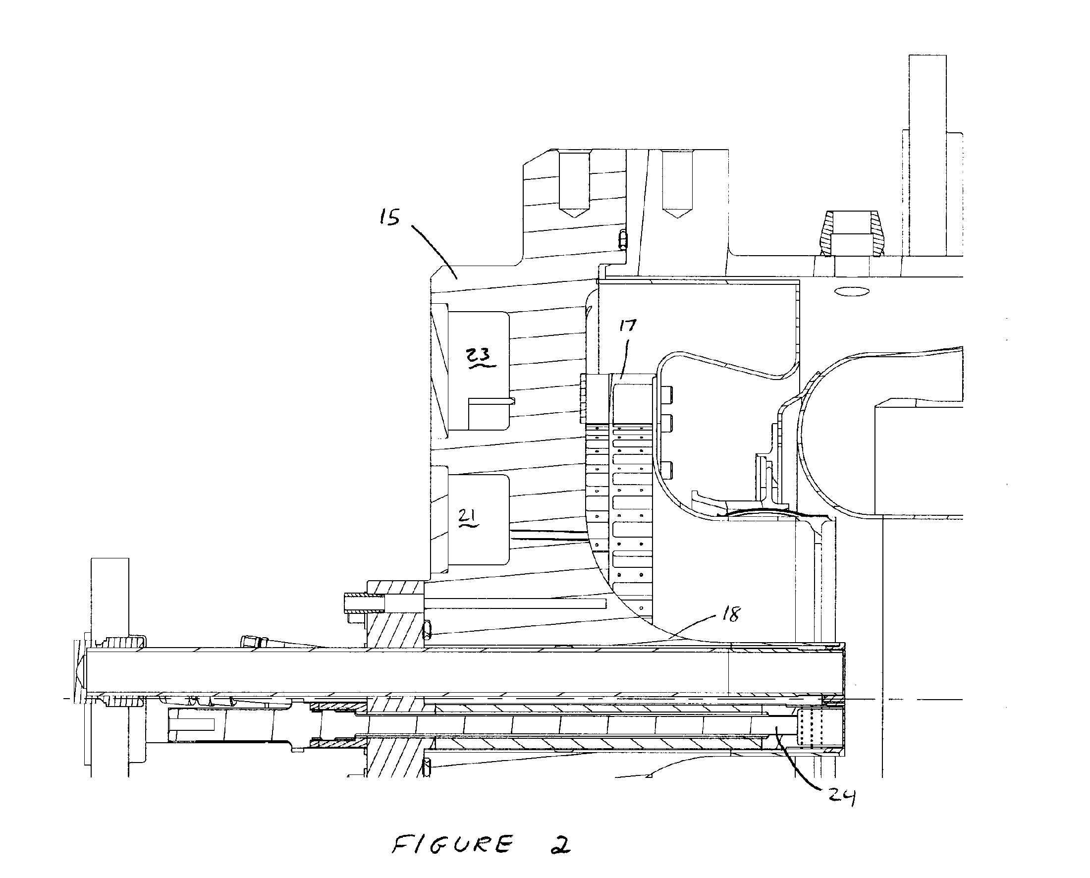
[0015] Referring now to FIGS. 2-4, further details of pilot fuel injection system 16 and its operation can be seen in greater detail. The pilot fuel injection system preferably comprises a radial inflow swirler 17 having at least one set of swirlers oriented generally perpendicular to a combustor centerline A-A (see FIG. 1). An additional feature of end plate 15 that is incorporated into pilot fuel injection system 16, and is shown in FIGS. 2-4, is an axially extending centerbody 18. This centerbody, which ...


PUM


Abstract

A gas turbine combustor having a self-purging pilot fuel injection system and method of operation thereof is disclosed. The pilot fuel injection system comprises a radial inflow swirler, a generally axially extending centerbody, and at least one fuel injection source. In operation a fluid containing at least air passes along the centerbody outer surface clearing any remaining fuel from proximate the fuel injection source so as to prevent flame attachment proximate the fuel injection source.

Description

BACKGROUND OF THE INVENTION [0001] The present invention is directed generally towards gas turbine combustors and more specifically towards an apparatus and method of providing a self-purging pilot fuel injection system. [0002] A typical gas turbine engine comprises at least a compressor, a turbine, and at least one combustor. The compressor takes air from the surrounding atmosphere and compresses it by directing it through a plurality of stages of rotating and stationary airfoils, raising its pressure and temperature. This compressed air is then directed into a combustion system, which is most commonly annular or can-annular, and comprises a plurality of fuel injectors. Fuel, either gas or liquid, is mixed with the compressed air and ignited to form hot combustion gases. The hot combustion gases are then directed through a multi-stage turbine, which is coupled to the compressor, and for power generation, to an electrical generator. [0003] The combustion system of the gas turbine en...

Claims


Application Information

Patent Timeline
IPC IPC(8): F02C7/22
CPCF02C7/22F23D2209/30F23R3/343F05D2260/60
Inventor STUTTAFORD, PETERJENNINGS, STEPHEN
Owner ANSALDO ENERGIA IP UK LTD
Why Eureka
Try Eureka