
Fastener tightening device

a technology of fastener and tightening device, which is applied in the direction of wrenches, metal-working devices, screwdrivers, etc., can solve the problems of increased weight of the bolt tightening device, increased difficulty in using the device, and large number of components, and achieves the effect of low cost and convenient us

Pending Publication Date: 2006-08-03
AISIN AW CO LTD
View PDF5 Cites 23 Cited by
  • Summary
  • Abstract
  • Description
  • Claims
  • Application Information

AI Technical Summary

Benefits of technology

[0010] Accordingly, it is an object of the present invention to provide a small, lightweight and low cost fastener tightening device that is easy to use and that can tighten a plurality of fasteners at the same time, regardless of where the fasteners are positioned.
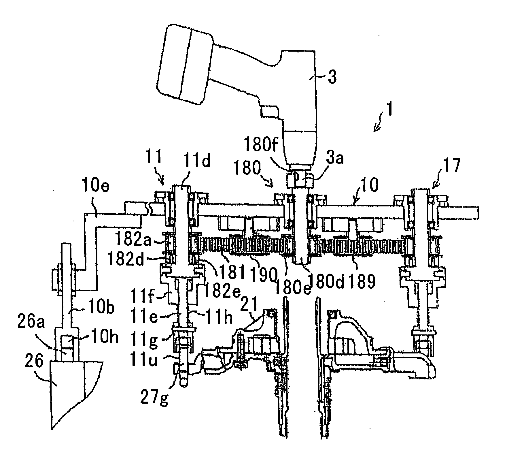
[0011] The device (tool) of the present invention is able to simultaneously tighten a plurality of fasteners and includes a plurality of rotary shafts including respective fastener holders; and a torque transmission unit that uses a single belt. Because the fastener tightening device of the present invention is able to transmit torque using a single belt, the number of components, the size and the weight of the device can be reduced. Further, since the device is lightweight it is easier to use. Torque from an external source may be input to one or more of the plurality of rotary shafts.
[0012] The device of the present invention may include a torque limiting unit that controls the torque of at least one of the plurality of rotary shafts, which allows the fasteners to be tightened to a predetermined torque. The torque limiting unit may control the pulleys on the rotary shafts to control the torque of the rotary shafts, making it possible to reliably tighten the fasteners to the predetermined torque.

Problems solved by technology

However, if the diameter of the gears is increased, the weight of the bolt tightening device is also increased, which makes it harder to use the device.
The above-described dual bolt tightening device includes the toothed belts 43, 44 for respectively driving the rotary shafts 41, 42, the toothed pulleys 45, 46 and the drive shaft 40, which amount to a large number of components and thus high cost.

Method used


Image

  • Fastener tightening device
  • Fastener tightening device
  • Fastener tightening device

Examples


Embodiment Construction

[0027] A preferred embodiment of the fastener tightening device of the present invention, used for attaching an oil pump assembly to an automatic transmission by simultaneously tightening seven bolts, will now be described with reference to the accompanying drawings.

(1) Overall Structure of the Automatic Transmission

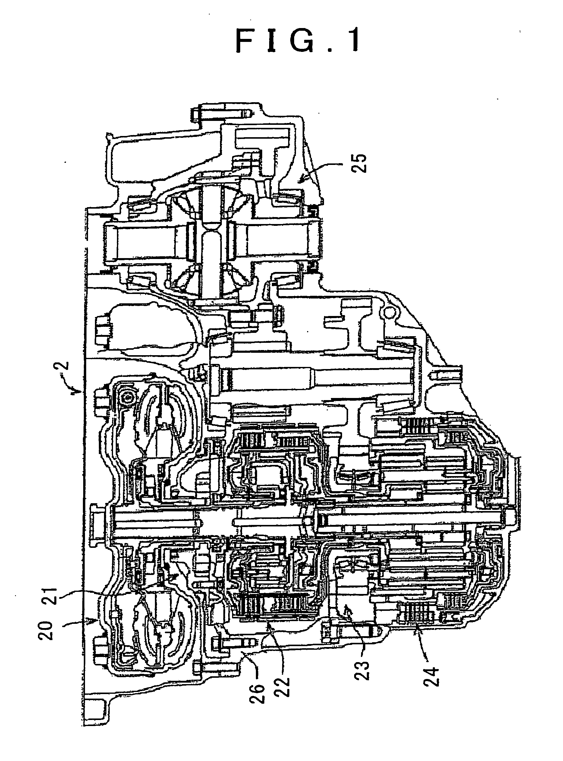
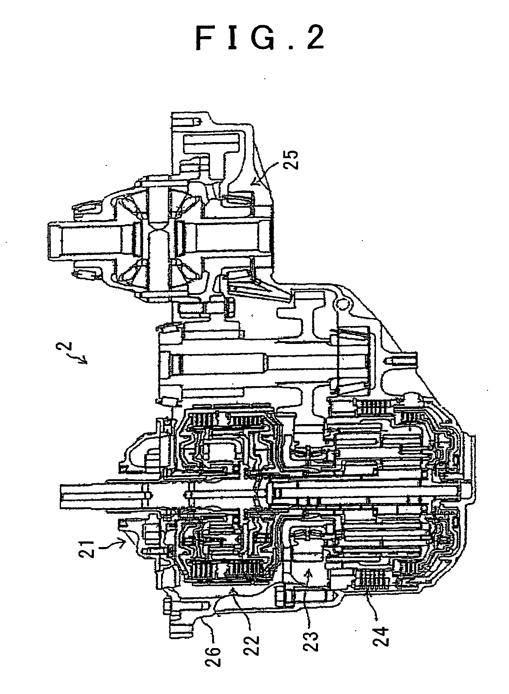
[0028] The overall structure of an automatic transmission on which the described preferred embodiment of the present invention is used is illustrated in FIGS. 1 to 3, and may be, for example, a front engine-front wheel drive (FF) vehicle or a rear engine-rear wheel drive (RR) vehicle. For example, the automatic transmission may be that disclosed in Japanese Patent Application Publication (“Kokai”) No. JP-A-2002-220704. Accordingly, although a general outline of the structure will be given here, a detailed explanation will be omitted.

[0029]FIG. 1 shows automatic transmission 2 as including a torque converter assembly 20, an oil pump assembly 21, a front sub-assembly 2...


PUM


Abstract

A bolt tightening device includes bolt tightening mechanisms, a torque input unit, a toothed belt and torque transmission units. The torque transmission units are provided with toothed pulleys and are integrated with the bolt tightening mechanisms. A toothed pulley is fixed to the torque input unit, and drivably connected to all the toothed pulleys of the plural torque input units by the single toothed belt. Torque input to the torque input unit is transmitted to the bolt tightening mechanisms by the toothed belt, and used to simultaneously tighten, for example, seven bolts. Because, torque can be simultaneously transmitted to plural bolt tightening mechanisms using a single belt, the number of components is reduced and the size, weight and cost are reduced and ease of use is improved.

Description

INCORPORATION BY REFERENCE [0001] The disclosure of Japanese Patent Application No. 2005-022293 filed on Jan. 28, 2005, including the specification, drawings and abstract, is incorporated herein by reference in its entirety. BACKGROUND OF THE INVENTION [0002] 1. Field of the Invention [0003] The present invention relates to a fastener tightening device that can simultaneously tighten a plurality of fasteners. [0004] 2. Description of the Related Art [0005] An oil pump assembly of an automatic transmission is fixed to the housing of the automatic transmission by a plurality of bolts. Devices for simultaneously tightening such a plurality of bolts are known in the art, such as the bolt tightening device described in Japanese Patent Application Publication No. JP-A-9-216172, and a dual side bolt tightening device displayed at the 2004 TPM Exhibition of Machinery Improvement Concepts. [0006] Such bolt tightening devices include a torque transmission unit and a plurality of rotary member...

Claims


Application Information

Patent Timeline
IPC IPC(8): B25B17/00B25B23/14B25B23/02B25B13/00
CPCB23P19/069B25B17/00
Inventor TANIGUCHI, TAKAOIKEDA, SHIGEHARUWATANABE, NOBUYOSHI
Owner AISIN AW CO LTD
Learn More