Spool braking device for dual-bearing reel

a braking device and reel technology, applied in the direction of electrodynamic brake systems, reels, vehicle components, etc., can solve the problems of braking the spool, heat generation of the coil, consumption, etc., and achieve the effect of suppressing the increase in the size of the reel

Inactive Publication Date: 2006-08-03
SHIMANO INC
View PDF2 Cites 22 Cited by
  • Summary
  • Abstract
  • Description
  • Claims
  • Application Information

AI Technical Summary

Benefits of technology

[0011] The object of the present invention is to provide a spool braking device for a dual-bearing reel that can supp...

Problems solved by technology

When the switch element is turned on, the electric power generated b...

Method used


Image

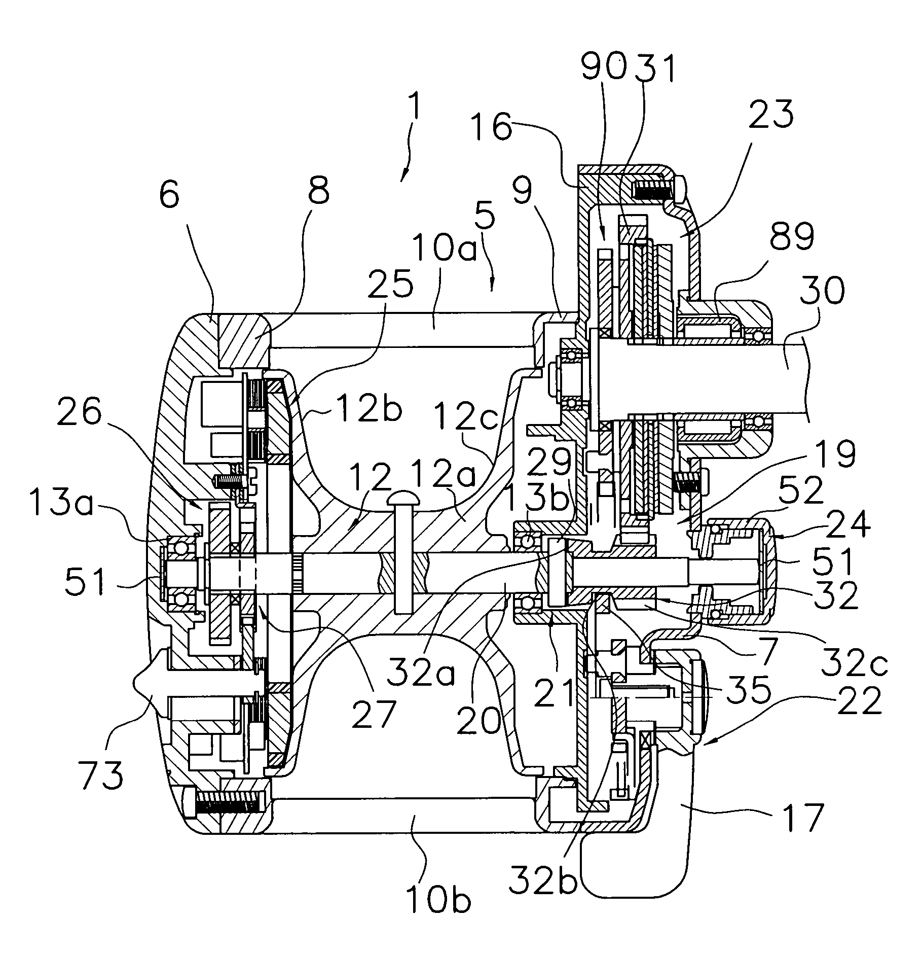
  • Spool braking device for dual-bearing reel
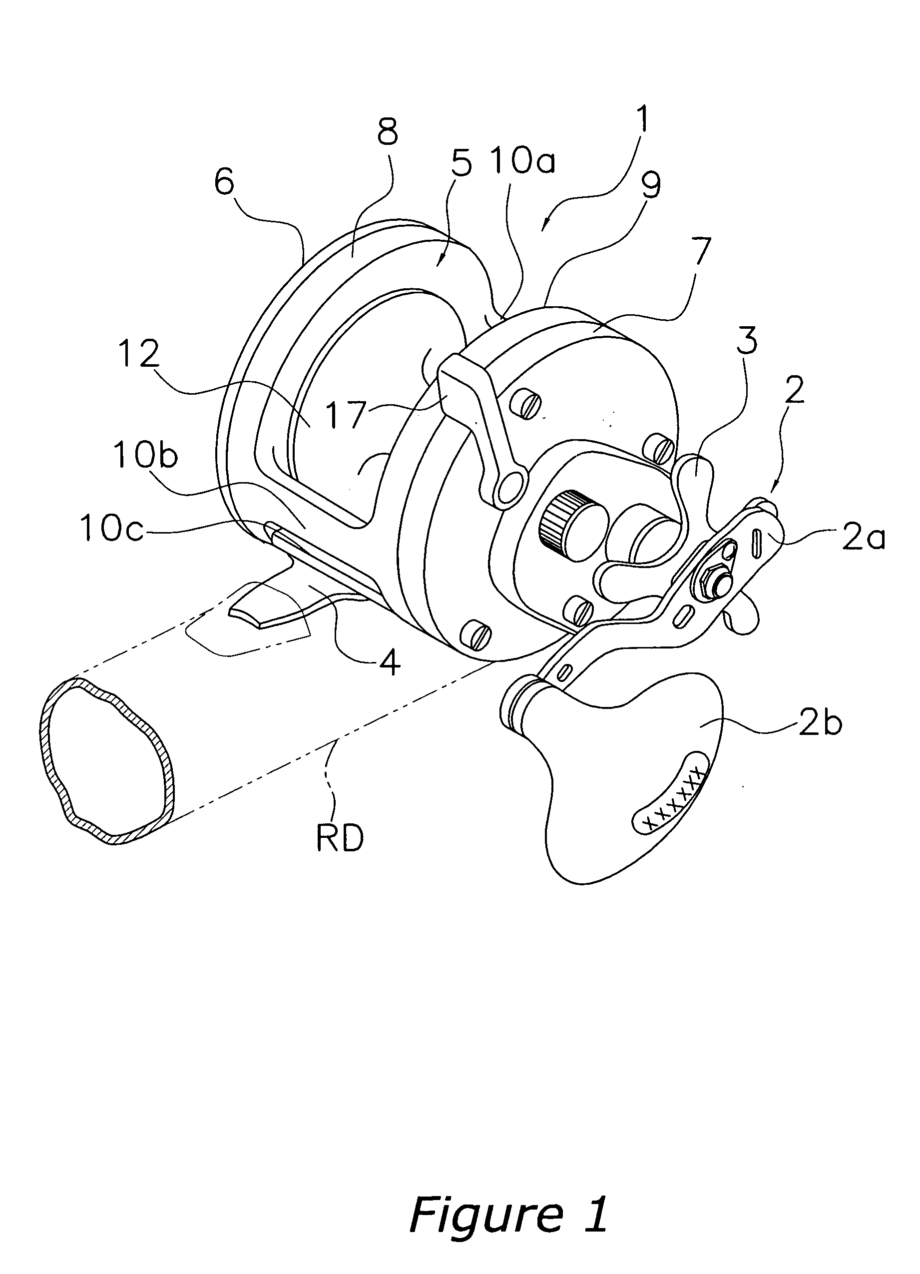
  • Spool braking device for dual-bearing reel
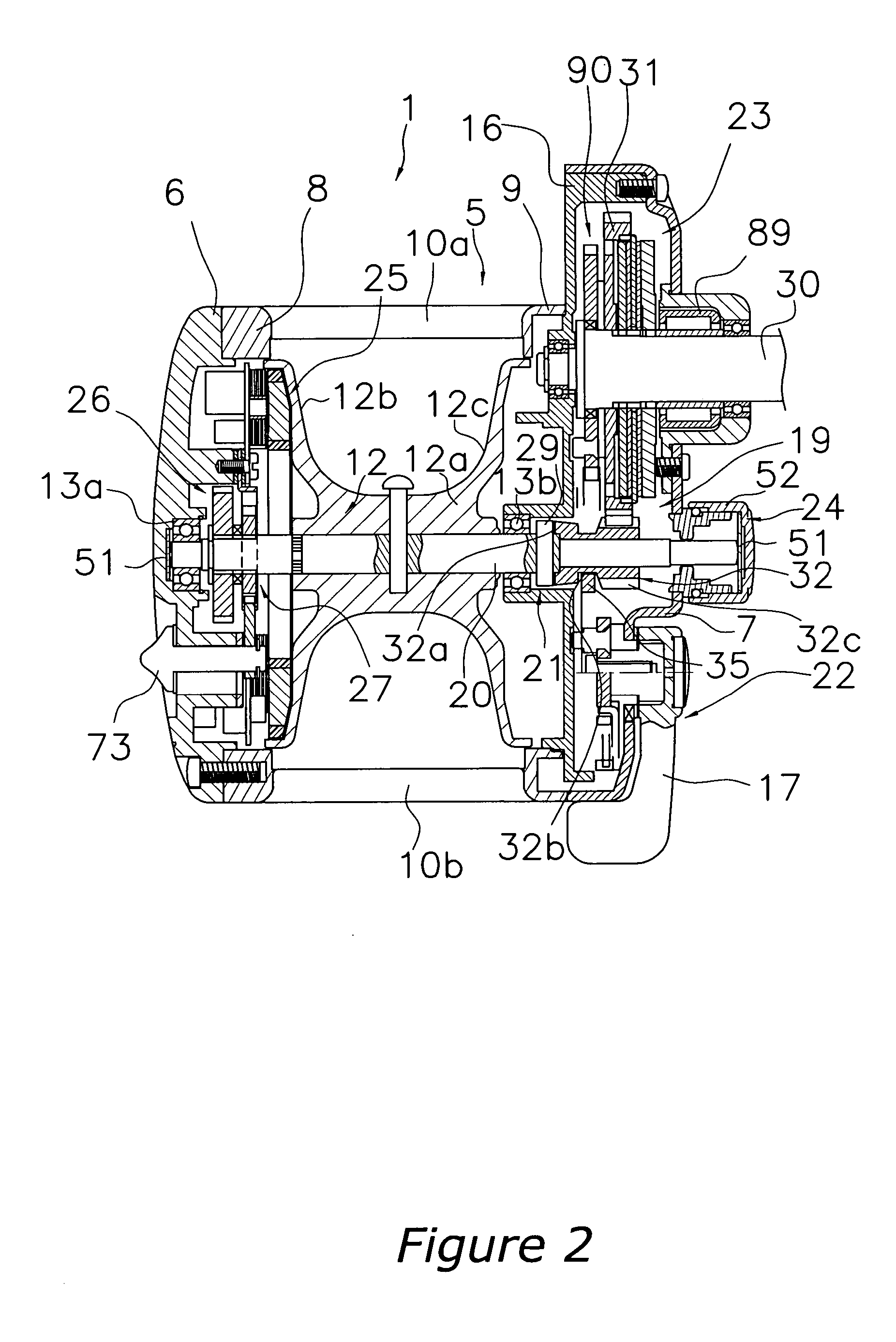
  • Spool braking device for dual-bearing reel

Examples


second embodiment

[0104] Referring now to FIG. 11, a spool braking device in accordance with a second embodiment will now be explained. In view of the similarity between the first and second embodiments, the parts of the second embodiment that are identical to the parts of the first embodiment will be given the same reference numerals as the parts of the first embodiment. Moreover, the descriptions of the parts of the second embodiment that are identical to the parts of the first embodiment may be omitted for the sake of brevity.

[0105] In the first embodiment the display unit 46 displays only the set mode of the spool braking mechanism 25 and the rotational velocity of the spool 12. The spool braking device of the second embodiment is the same as the first embodiment except a manually operated part 46e″ is provided in a display unit 46″, as shown in FIG. 11. The manually operated part 46e″ is for changing the content displayed on the display unit 46″. The display unit 46″ is configured to display va...

third embodiment

[0106] Referring now to FIG. 12, a spool braking device in accordance with a third embodiment will now be explained. In view of the similarity between the first and third embodiments, the parts of the third embodiment that are identical to the parts of the first embodiment will be given the same reference numerals as the parts of the first embodiment. Moreover, the descriptions of the parts of the third embodiment that are identical to the parts of the first embodiment may be omitted for the sake of brevity.

[0107] In the third embodiment, a ring shaped forming magnet 261 has a plurality of magnetic poles 261a. The ring shaped forming magnet 261 is provided in a rotor 260. The ring shaped forming magnet 261 is made of a molded resin mixed with metal particles or molded sintered metal.


PUM


Abstract

A spool braking device for a dual-bearing reel that applies a braking force to a spool during casting includes a spool brake unit, a switch element, a casting state detecting device and a spool control device. The spool brake unit is configured to brake the spool and includes a rotor having a plurality of magnets and a plurality of coils. The magnets are arranged along a rotational direction with alternating polarities. The coils are arranged to be spaced apart in a circumferential direction. The coils have end faces that are arranged to face a side face of the rotor. Each of the coils has a winding diameter that is larger than a full length of the coil. The casting state detecting device is configured to detect a casting state. The spool control device is configured to control an on/off status of the switch element based on the casting state.

Description

CROSS-REFERENCE TO RELATED APPLICATIONS [0001] This application claims priority to Japanese Patent Application Nos. 2005-010201 and 2005-053579. The entire disclosure of Japanese Patent Application Nos. 2005-010201 and 2005-053579 is hereby incorporated herein by reference. BACKGROUND OF THE INVENTION [0002] 1. Field of the Invention [0003] The present invention generally relates to a spool braking device. More specifically, the present invention relates to a spool braking device for a dual-bearing reel that is used during casting and is configured to brake a spool in an electrically controllable manner. [0004] 2. Background Information [0005] Conventional electrically controllable spool braking devices have a spool brake unit and a spool control unit, which is configured to electrically control the spool brake unit. (See, for example, Japanese Laid-Open Patent Publication No. 11-332436.) [0006] In this spool braking device, the spool brake unit has a plurality of magnets, a plurali...

Claims


Application Information

Patent Timeline
IPC IPC(8): A01K89/02
CPCA01K89/01555Y10S43/00
Inventor NAKAGAWA, SHOUJIIKUTA, TAKESHIKAWASAKI, KEN'ICHIKURIYAMA, HIROAKI
Owner SHIMANO INC
Why Eureka
Try Eureka