Method and apparatus for manufacturing a trailer wall and wall formed thereby

a technology of trailer walls and manufacturing methods, applied in the field of trailer walls, can solve the problems of increasing wind resistance, reducing aesthetic appeal, and skin wear and tear

Inactive Publication Date: 2006-08-03
MAC TRAILER MFG
View PDF26 Cites 22 Cited by
  • Summary
  • Abstract
  • Description
  • Claims
  • Application Information

AI Technical Summary

Benefits of technology

[0019]FIG. 7 is a rear elevational view of the truck with portions cut away to show the trailer wall from the rear end.

Problems solved by technology

One disadvantage of this configuration is that objects such as the cargo may create dents from inside the trailer which show on the outside, thus reducing aesthetic appeal and increasing wind resistance.
In addition, there is a tendency for the skin to wear out over time.
In comparison to horizontal planks, these vertical planks generally require more pieces to create a given wall, thereby lengthening the assembly period for such a wall.
Further, vertical joints are less preferable for use with trailer walls used on a dump truck, as the vertical joints create wear areas as the material in the truck abrades the wall at the joints when dumped rearwardly in a direction generally perpendicular to the vertical joints.
In addition, the manufacture of certain trailer walls present several problems.
However, using additional clamps along the length of the wall member is labor intensive and thus not very cost-effective.
In addition, where the wall members are hollow, clamping along the length of the wall member may increase the risk of damage to the skin of the hollow wall member.
Where several wall members are positioned adjacent one another on a work surface, the combined width of the wall members makes clamping even more impractical for the interior wall members and may require clamps having extended jaws which would interfere with welding or other joining procedures.
Second, when the wall members are joined by welding, the heat created by welding leads to bowing of the wall formed thereby.
This bowing can be quite substantial in certain circumstances and may even make the joined wall members unusable for their intended purpose.

Method used


Image

  • Method and apparatus for manufacturing a trailer wall and wall formed thereby
  • Method and apparatus for manufacturing a trailer wall and wall formed thereby
  • Method and apparatus for manufacturing a trailer wall and wall formed thereby

Examples


Embodiment Construction

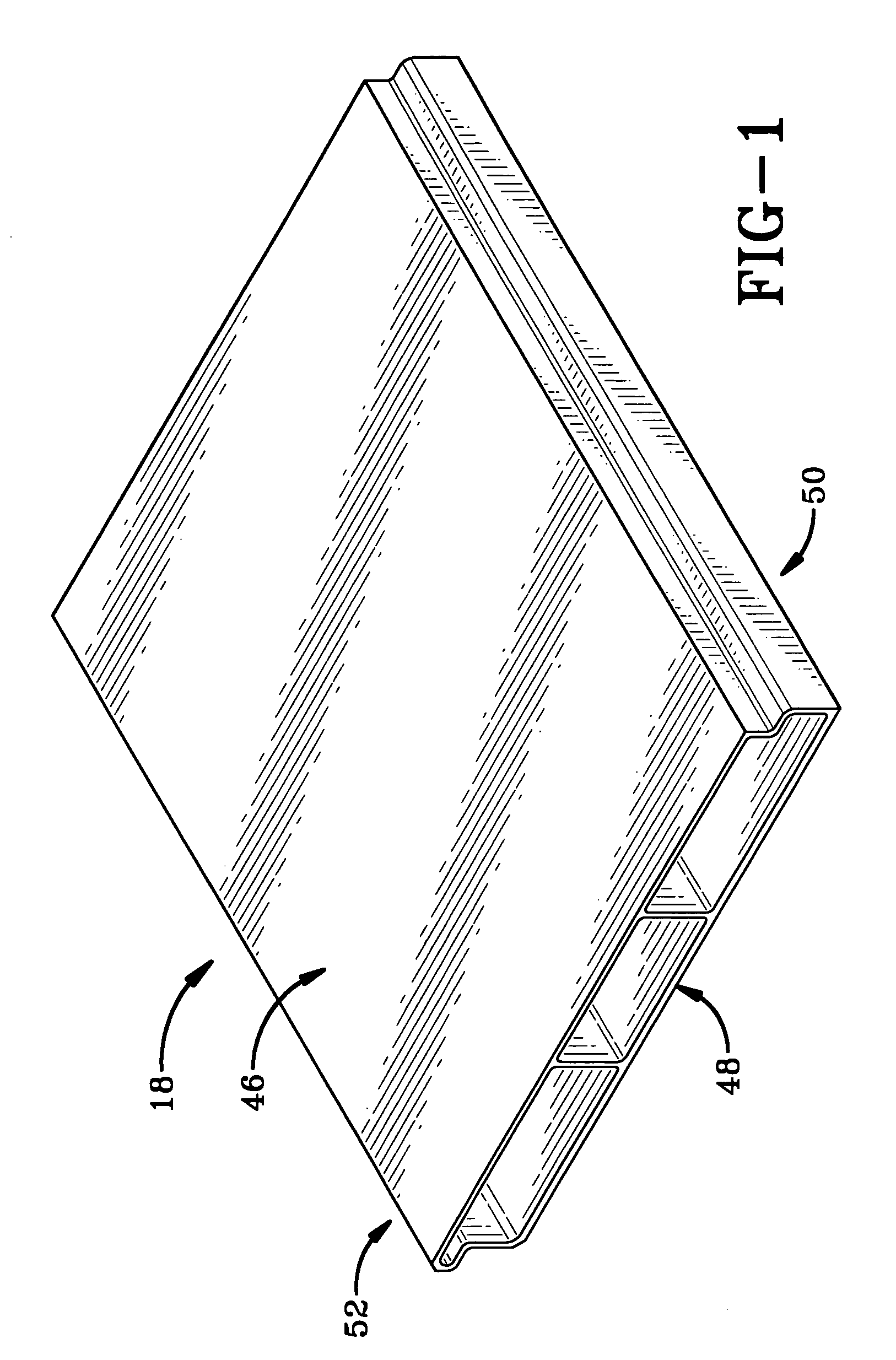
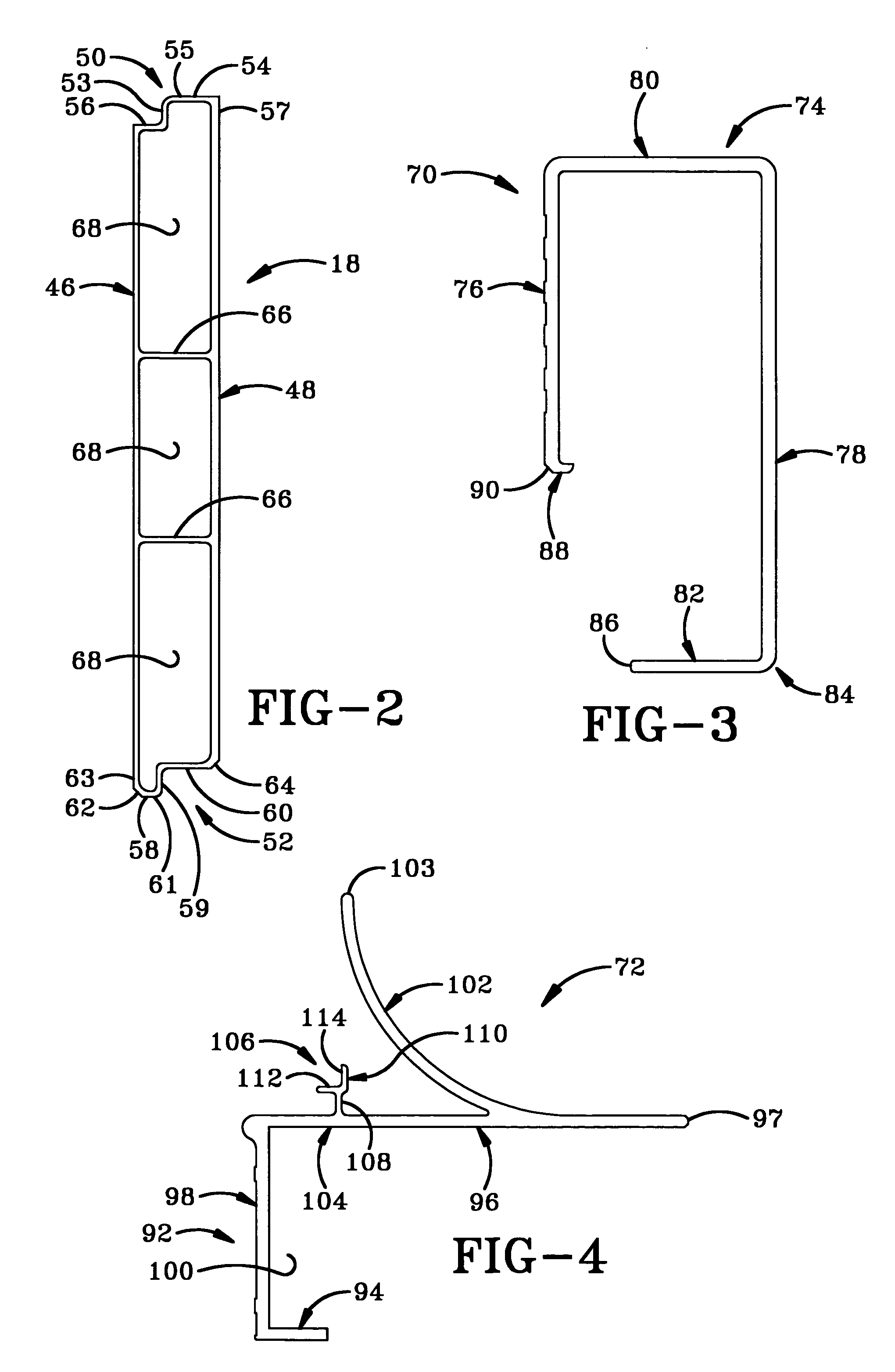
[0037] The panel of the present invention used in forming a trailer wall is indicated generally at 18 in FIGS. 1-2. Each hollow panel 18 takes the general form of a shiplap with overlapping edges. Panel 18 includes a pair of opposed walls or sides which are substantially flat and parallel to one another and elongated in the elongated direction of panel 18. These opposed walls constitute an outer wall 46 and an inner wall 48 which is thicker than outer wall 46, although walls 46 and 48 may have the same thickness or vary as desired. Preferably, inner wall 48 is disposed along the interior of the trailer to resist denting due to shifting cargo and the like and to provide additional material for a more durable wall. Panel 18 further includes a first connecting side 50 with an overlapping configuration and a second connecting side 52 with an overlapping configuration in opposed relation to first connecting side 50.

[0038] The first connecting side 50 of one panel 18 is configured to mat...


PUM

PropertyMeasurementUnit
pressureaaaaaaaaaa
lengthaaaaaaaaaa
resistanceaaaaaaaaaa

Abstract

A method for manufacturing a trailer wall includes welding wall members together on a work surface while pressing the wall members with a rotatable roller toward the work surface and cooling the wall members adjacent points of welding there between to reduce bowing of the wall members related to heat created in the wall members by the welding. A related apparatus includes a movable welding unit having a welding tip for welding a pair of wall members together at a plurality of locations while on a work surface. A rotatable roller is pivotally mounted on the welding unit for applying pressure to the wall members toward the work surface adjacent the welding tip while rolling along the wall members. A cooling unit moves liquid or gas coolant to provide the cooling effect. Preferably, the wall members are hollow shiplap panels and the coolant passes through the hollow panels.

Description

CROSS REFERENCE TO RELATED APPLICATIONS [0001] This application claims priority from U.S. Provisional Application Ser. No. 60 / 648,853 filed Feb. 1, 2005; the disclosure of which is incorporated herein by reference.BACKGROUND OF THE INVENTION [0002] 1. Technical Field [0003] The invention relates to trailer walls, such as those used with tractor trailers, and a method of and apparatus for manufacturing the same. More particularly, the invention relates to the use of hollow wall members and a method of welding the wall members together. Specifically, the invention relates to such hollow wall members having a ship-lap configuration and such a method and apparatus which prevent bowing of the wall during welding. [0004] 2. Background Information [0005] The construction of trailer walls and the structural elements used therein come in a variety of forms. For example, some trailer walls are formed with a plurality of vertical support members with a metal skin attached on the outside thereo...

Claims


Application Information

Patent Timeline
Patent Type & Authority Applications(United States)
IPC IPC(8): B62D25/02
CPCB23K33/008B62D33/046
Inventor CONNY, MICHAEL A.MAIORANA, JAMES A.ARNOLD, JAMES S.
Owner MAC TRAILER MFG
Why Eureka
Try Eureka